What Is DFM in Die Casting?
DFM in die casting refers to a systematic methodology focused on optimizing the geometry of a part to ensure stable filling, predictable solidification, and reliable mechanical performance. In high-pressure die casting, molten metal is injected into a steel mold at high velocity and pressure. The way the metal flows, cools, and solidifies is highly sensitive to wall thickness, corner radii, rib placement, and other structural features. DFM analysis is a preventive approach: it evaluates manufacturability before tooling is produced, helping engineers reduce iterative mold modifications and improve part consistency.
Why DFM for Die Casting is Important?
Custom die casting parts involve complex interactions between geometry, thermal dynamics, and fluid behavior. Features such as uneven wall thickness, sharp internal corners, and poorly positioned ribs can create turbulence, thermal hotspots, or stress concentrations, resulting in defects such as porosity, shrinkage, or warping.
Applying DFM early allows engineers to identify these risks during the prototype phase, which helps prevent costly tooling revisions and reduces scrap rates. Ultimately, DFM ensures that the design is both functionally sound and reliably manufacturable within the constraints of the casting process.
Core DFM Guidelines for Die Casting
Design for Manufacturability (DFM) ensures that die-cast parts are designed for smooth metal flow, reliable filling, and minimal defects. By applying DFM principles early, engineers can optimize wall thickness, draft angles, fillets, ribs, bosses, and parting lines to improve manufacturability and production consistency. Proper DFM not only reduces the risk of defects and tooling revisions but also helps control die casting cost, as well-designed geometry minimizes scrap, reduces secondary machining, and shortens production cycles.
Wall Thickness Control
Maintaining uniform wall thickness is one of the most critical aspects of die casting design. If the wall is too thin, molten metal may fail to fill the cavity completely, resulting in coarse microstructure and weak mechanical properties. Conversely, excessively thick walls cool unevenly, producing shrinkage cavities, porosity, or surface depressions that compromise part strength and dimensional stability.
For aluminum and magnesium die-cast parts with moderate surface areas, the optimal wall thickness is generally between 1.5 and 2.5 millimeters, while zinc parts typically require 1.0 to 2.0 millimeters. Designers should also control the ratio between the thickest and thinnest sections, keeping it below 3:1. Sudden transitions in wall thickness should be avoided, and smooth gradients should be used to reduce stress concentrations and minimize warping or cracking during solidification.
Draft Angle Design
Draft angles are slight tapers on vertical surfaces that facilitate part ejection from the mold. Properly designed draft angles reduce friction, prevent surface scratches, and extend mold life. The required draft varies depending on the material, surface finish, and depth of features. Aluminum tends to adhere more strongly to molds, so larger draft angles—typically around 1° on internal surfaces—are recommended. Magnesium requires approximately 0.75°, while zinc can often use 0.5° or more.
Textured or deep features require slightly larger draft angles to allow smooth ejection without damaging the casting. In general, internal surfaces benefit from slightly larger drafts than external surfaces. Correct draft design ensures parts release cleanly from the mold, reducing defects and improving production efficiency.
Fillets and Transition Radius
Sharp internal corners restrict molten metal flow and create stress concentration points, increasing the risk of cracks or weak sections. Rounded fillets help maintain smooth flow, reduce turbulence, and facilitate gas escape. For internal corners, the radius is typically recommended to be at least equal to the local wall thickness. External fillets should balance smoothness with overall wall uniformity to avoid excessively thick areas that can cause shrinkage or gas defects. Proper fillet design also improves the durability of the mold and ensures uniform plating or coating if the part undergoes secondary finishing.
Rib Design Optimization
Ribs are used to enhance structural strength without significantly increasing wall thickness. The thickness of ribs should generally be 50–70% of the adjacent wall thickness, and their height should be limited to no more than five times the wall thickness. Rib roots should include rounded corners to prevent stress concentration, and ribs should be oriented in line with the flow of molten metal. Care should be taken to distribute ribs symmetrically and avoid thick intersections, which can create localized shrinkage defects. Well-designed ribs improve rigidity, resist deformation, and aid metal flow during filling.
Boss Design Guidelines
Bosses are frequently used for mounting points or assembly interfaces but are common sites for porosity due to localized material accumulation. The wall thickness of bosses should not exceed that of the surrounding structure, and they should be connected to the main walls with ribs to provide support and prevent sink marks. Adequate draft and fillets at the base of the boss help ensure proper filling and reduce defects.
Parting Line Design Principles
The parting line is where the two halves of the mold meet. A well-positioned and simple parting line improves casting quality and simplifies mold construction. Flat parting lines are preferred for most components, while stepped or curved lines should be minimized unless required by geometry. The parting line should not cross critical datum surfaces, and its placement should allow smooth flow of metal and gas venting during filling. Coordinating the parting line with gates and overflow channels ensures uniform casting quality.
Undercut and Hole Orientation Optimization
Undercuts and side holes can complicate mold design and require sliders, increasing cost and potential for defects. Designers should minimize undercuts or orient holes perpendicular to the parting line when possible. Reducing complex slider requirements helps maintain mold simplicity and improves part manufacturability.
Tolerance Design within Casting Capability
Tolerances must be aligned with the natural capability of the die casting process. Excessively tight tolerances increase mold wear, raise scrap rates, and may require secondary machining. Functional requirements should guide tolerance specification, with allowances made for variations inherent to high-pressure die casting. Matching tolerance to process capability ensures reliability without unnecessary cost.
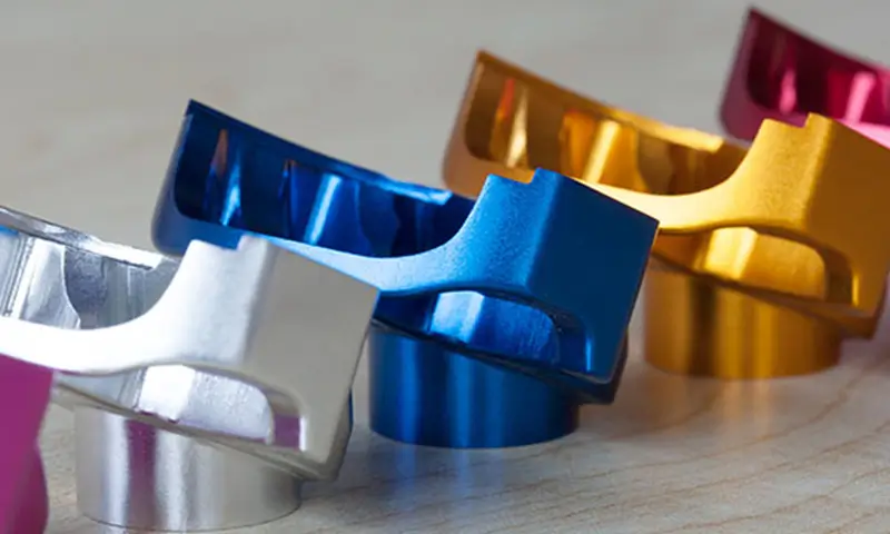
Material Selection for Manufacturability
Selecting the right material is critical in die casting design, as it affects metal flow, solidification, shrinkage, and overall castability. The material must meet mechanical, environmental, and thermal requirements while being compatible with the part geometry and production process. For engineers comparing alloys, understanding the aluminum vs zinc die casting properties can help make informed material choices for optimal manufacturability.
Aluminum alloys are widely used for their strength, corrosion resistance, and good flowability, making them suitable for medium- to large-sized parts with complex features.
Magnesium alloys are lightweight and corrosion-resistant, ideal for applications where weight reduction is essential, such as automotive or aerospace components.
Zinc alloys allow fine details and smooth surface finishes, solidifying quickly, which makes them well-suited for small parts with intricate geometries.
Ejection Design Principles
Proper ejection ensures parts are removed smoothly after solidification. Ejector pins should be placed on non-critical surfaces, distributing force evenly to prevent distortion. Placement must coordinate with draft angles, parting line, and material. Correct ejection reduces defects, protects mold life, and improves production efficiency.
Get a DFM Review & Transparent Quote
Submit your drawings to receive a detailed manufacturability assessment along with a clear and itemized quotation. Our engineers help optimize your design while ensuring pricing transparency and production feasibility.
Get QuotePrototype Validation Strategy
Prototype validation ensures that die-cast designs perform as intended before full-scale tooling. By using CNC prototypes, 3D printing, soft tooling, and mold flow simulation, engineers can identify manufacturability issues, verify structural integrity, and optimize geometry. Early validation reduces mold revisions, minimizes defects, and improves production readiness.
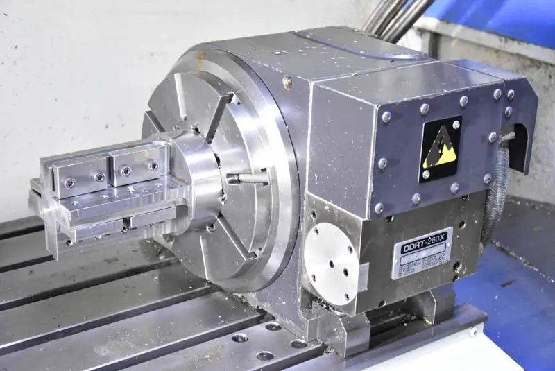
CNC Prototype Engineering Testing
CNC prototypes are widely used for structural verification, allowing engineers to assess mechanical strength, assembly compatibility, and dimensional fit before investing in tooling. Although machining differs from casting, the mechanical behavior of the structure can still be effectively analyzed, providing valuable insights for design adjustments.
3D Printing Geometry Verification
Additive manufacturing enables rapid prototyping for early design evaluation. It allows quick iterations to validate overall geometry and form, helping identify potential design issues. However, 3D-printed parts cannot fully replicate the metallurgical behavior of die-cast components, so they serve mainly for visual and structural assessment.
Soft Tooling Trial Manufacturing
Soft tooling supports low-volume production and manufacturability validation before investing in hardened steel molds for mass production. As a bridge between prototype testing and full-scale production, it enables evaluation of metal flow, filling behavior, ejection performance, dimensional stability, and assembly fit under near-production conditions. Typically made from aluminum or lower-grade tool steel, soft tooling reduces lead time and upfront investment while providing critical process data to minimize risk before final tooling commitment.
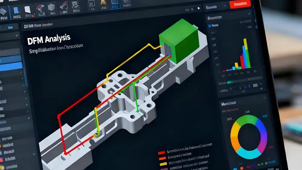
Mold Flow Simulation Analysis
Mold flow simulation predicts metal flow, cooling, and potential defect formation, guiding DFM adjustments before mold fabrication. Simplifying complex features, aligning wall thickness, and matching tolerances to process capability reduces defects and unnecessary secondary machining, improving both quality and production efficiency.
ZH Precision’s Die Casting DFM Engineering Support
ZH Precision offers comprehensive DFM Die Casting evaluation, CNC prototype testing, and mold flow simulation to ensure die-cast parts are manufacturable and meet quality standards. Our engineering support helps optimize part geometry, minimize tooling modifications, and improve first-pass yield, accelerating the transition from design to full-scale production.
Conclusion
DFM is essential in die casting, as most defects and cost risks originate from early design decisions. Applying systematic principles—covering wall thickness, draft angles, fillets, ribs, bosses, parting lines, and ejection—ensures consistent quality, reduces mold modifications, and accelerates production readiness. Prototype validation and manufacturability analysis translate concepts into reliable, high-quality die-cast components.
FAQ
A:Aluminum/magnesium: 1.5–2.5 mm; zinc: 1.0–2.0 mm.
A:Aluminum: ≥1°, magnesium: ≥0.75°, zinc: ≥0.5°, adjusted for surface texture and depth.
A:Only within process capability; overly tight tolerances increase mold wear and may require secondary machining.
A:Uniform wall thickness, proper rib/boss design, sufficient draft, and adequate venting reduce porosity risk.