
Engineering Drawing Symbols: Chart, Meanings and Examples
Engineering drawing symbols communicate requirements that a part’s outline cannot show on its own. A
Engineering drawing symbols communicate requirements that a part’s outline cannot show on its own. A

CNC fixtures locate, support, and hold workpieces while cutting tools remove material. Vises, soft jaws,

Low-volume CNC machining supports projects that need a small batch of functional parts for pilot

Die casting porosity refers to voids within a cast part, caused by trapped gas or

Sheet metal gauge indicates nominal thickness, but the same gauge number can represent different thicknesses

Sheet metal parts are widely used in consumer electronics, medical devices, automotive products, and industrial
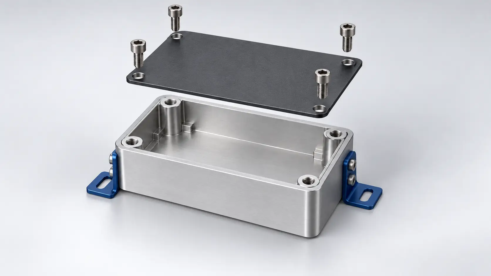
Design for assembly (DFA) brings assembly considerations into the earliest stages of product design. It
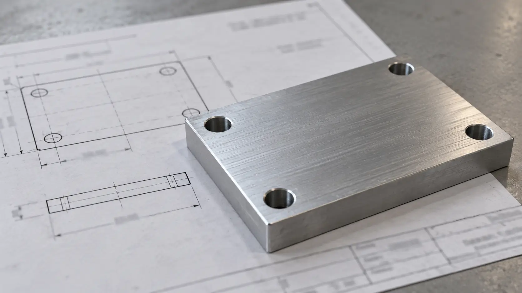
GD&T (Geometric Dimensioning and Tolerancing) is a system of symbols and rules used on technical
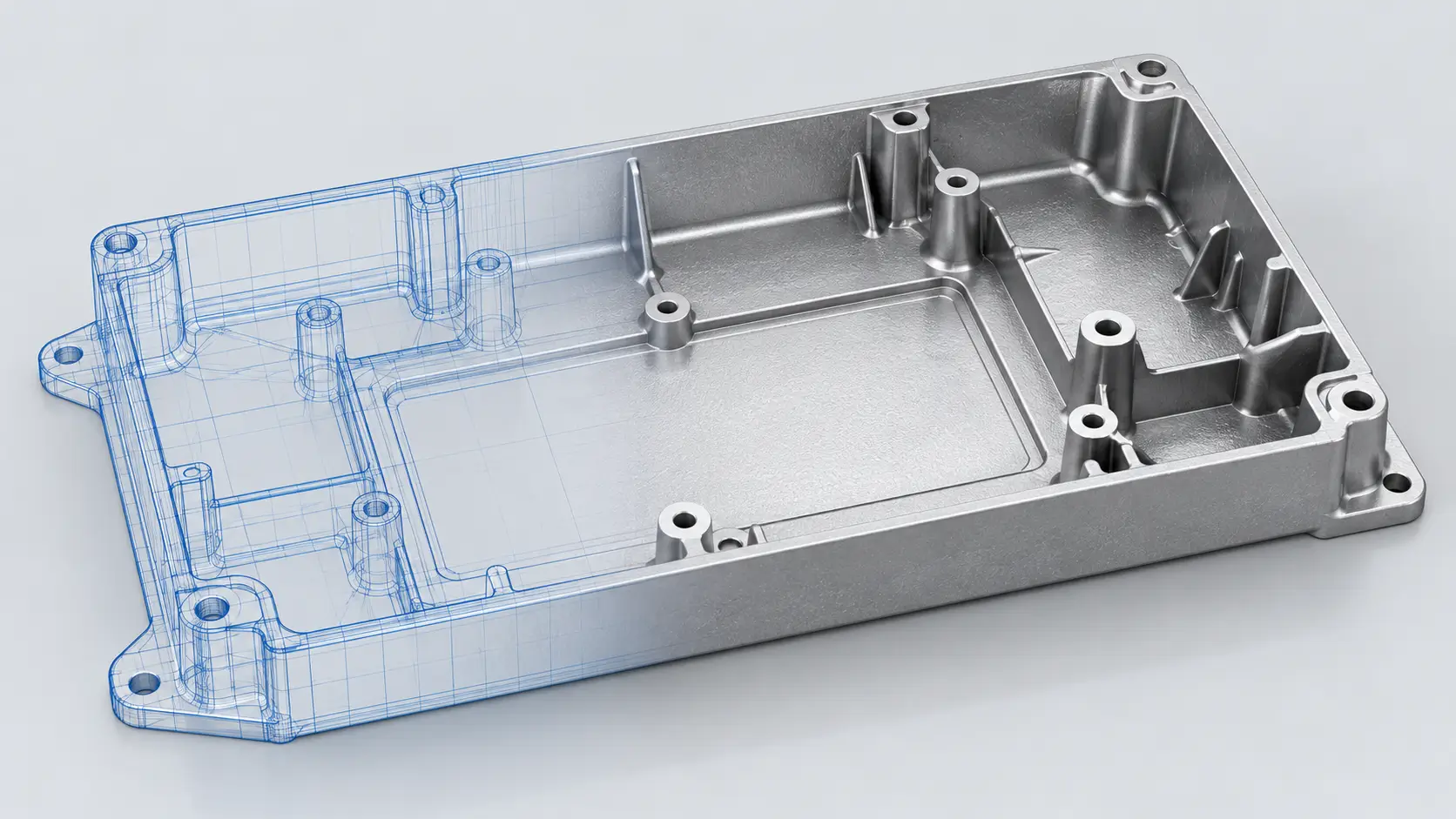
Die casting design determines how a metal part fills, solidifies, releases from the mold, and
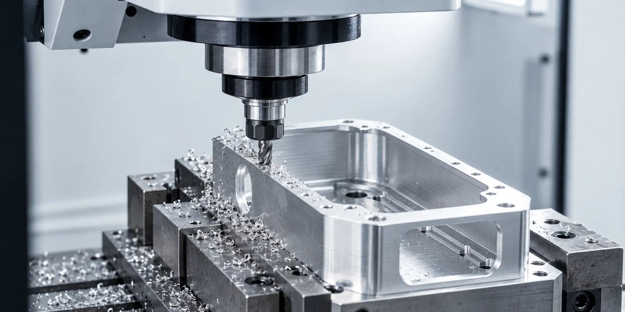
A metal housing may need a recessed cavity, a flat mounting face, and holes on
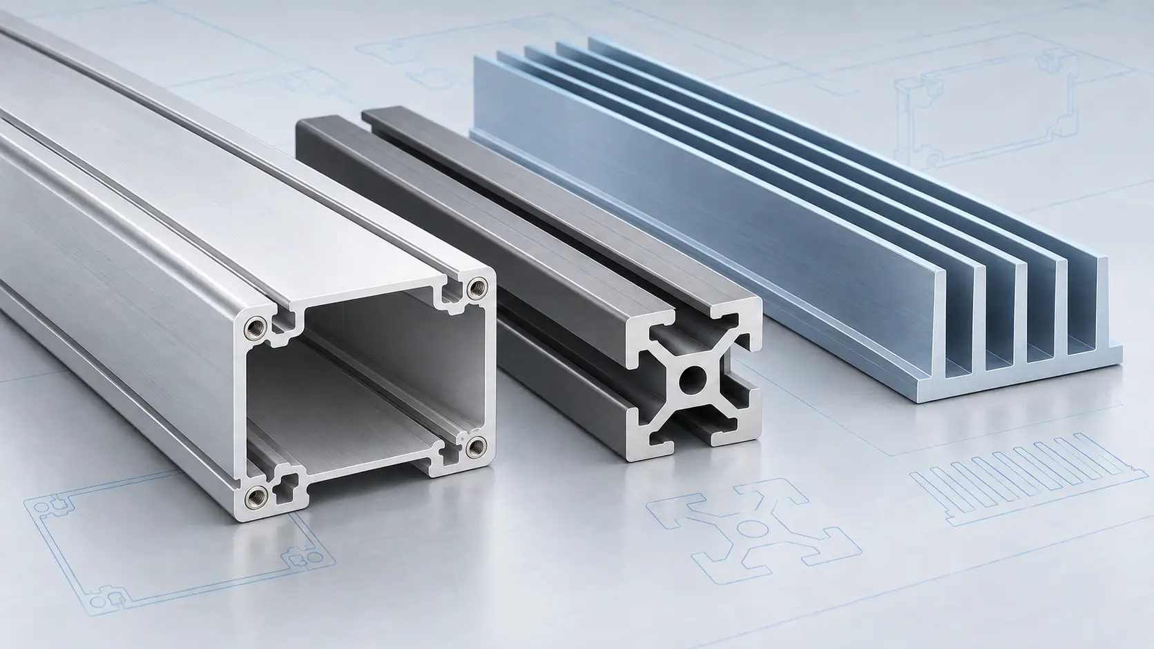
An aluminum profile can look straightforward in CAD yet be difficult to extrude or assemble.
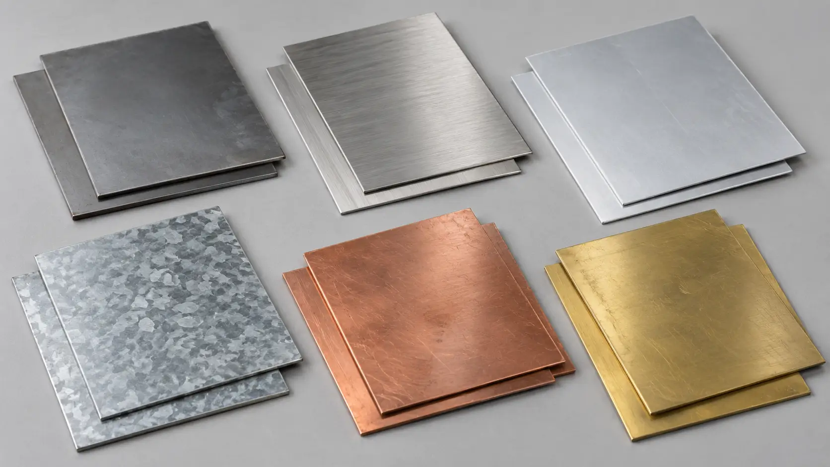
Steel, stainless steel, aluminum, copper, and brass are common sheet metal materials, each offering different