What is CNC Machining DFM?
CNC Machining DFM involves considering manufacturability during the design stage. It evaluates whether part features are easy to machine, whether tools can access all areas, whether tolerances are achievable, and whether production costs are reasonable. Following DFM principles helps avoid common issues such as deep pocket challenges, thin-wall deformation, or sharp corners that wear out tools.
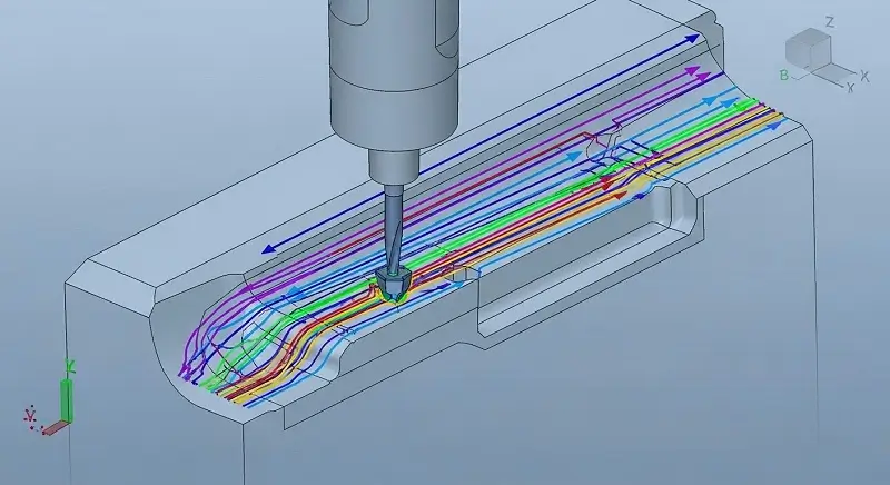
Avoid Deep Pockets
Deep-narrow pockets or slots must be machined by longer tools, which are more prone to breakage and can cause chatter, or machine vibrations. Additionally, it takes several passes to machine a deep pocket, which drives up machining time and manufacturing costs.
Recommendation: Avoid designing parts with deep pockets whenever possible. If a deep pocket cannot be avoided, engineers and designers should decrease its depth as much as possible or increase the cross-section area of the pocket. Remember that you may need smaller tools to complete finishing passes. As a rule, pocket depth shouldn’t exceed 3x the diameter of the smallest tool needed for the final feature. For example, pockets should be no deeper than 1.5″ (38.1 mm) when using a 0.5″ (12.7 mm) cutter. Engineers may have to adjust this figure based on the material they are using and the tools that are available to them.
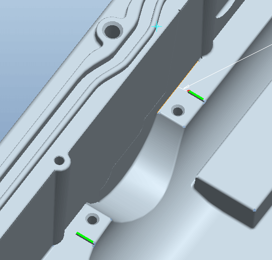
Eliminate Narrow Regions
Narrow regions are difficult to manufacture because the size of the cutter is restricted by the smallest distance between the various faces of the feature. Long and small diameter cutters are prone to breakage and chatter.
Recommendation: Avoid designing features or faces that are too narrow for a cutter to easily pass through. If narrow regions cannot be avoided, however, they must not be too deep. Remember that the depth of any feature should be less than 3x the diameter of the smallest tool needed for the final feature. As a best practice, wall sections should be greater than 0.03″ (0.762 mm) thick. A shorter cutter with a larger diameter can also be employed to reduce chatter.
Replace Sharp Corners with Radii
Since all CNC drill bits are circular, it’s difficult to achieve sharp internal corners. Instead, the drill bit will leave behind a pocket of unmachined space called an internal corner radius. It’s possible to machine sharp internal corners using workarounds, like electrical discharge machining, but these methods tend to be expensive.
Recommendation: Avoid sharp inside corners whenever possible. Ideally, a corner radius needs to be slightly larger than the cutter. If a corner radius is the same diameter as the cutter being used to form it, it can cause chatter and premature tool wear.
Increasing the corner radius beyond the standard value by as little as 0.005″ (0.127 mm) can give the tool enough room to move around and follow a more circular path.
Ensure Features Are Accessible
Inaccessible features like counterbores that open inside another pocket or pockets with negative drafts take longer to machine — if they’re even possible — because the cutting tool cannot easily access them, which in turn drives up costs.
Recommendation: You should ensure a cutting tool has full access to all features within a part without being blocked by another feature.
Chamfer Outside Edges
Outside fillets, or fillets on the top edges of pockets, bosses, and slots, require an exceptionally sharp cutter and a precise setup. Both of these requirements can be prohibitively expensive for some product teams. To avoid incurring these costs, bevel or chamfer — rather than fillet — the outside edges of features.
Maintain Minimum Wall Thickness
When it comes to CNC machining with metal, thin walls increase chatter, which can compromise the accuracy of the machining process and the surface finish of the part. With plastics, thin walls can cause warping and softening. As such, you should do your best to avoid designing parts with thin walls.
Recommendation: The ideal minimum wall thickness for metals is 0.03″ (0.762 mm) and 0.06″ (1.524 mm) for plastics. You may be able to achieve thinner sections without significant risk, but this needs to be assessed on a case-by-case basis.
Use Standard Hole Bottoms
Flat-bottomed holes require advanced machining operations and often cause problems down the line for subsequent operations like reaming. Avoid creating blind holes with a flat bottom — especially small holes — and instead use a standard twist drill to create holes with cone-shaped bottoms. Cone angles are commonly 118° or 135°.
Design for Easy Drill Entry and Exit
A drill tip will wander when it comes into contact with the material’s surface if that surface isn’t perpendicular to the drill axis. Uneven exit burrs around the exit hole will also make removing the burr difficult. To ease entry and exit, avoid designing hole features with start and end faces that are not perpendicular to the drill’s axis.
Consult a DFM Expert
Designing for manufacturability accelerates the CNC machining process, reduces operating costs, elevates energy efficiency, and helps product teams create clean, functional parts. Refer to this short checklist often to make sure your designs are on the right track, but an experienced manufacturing partner like ZH Precision can offer more nuanced insights.
ZH Precision Team assists engineers, designers, and product teams in ensuring their designs meet manufacturability requirements. We leverage cutting-edge digital design technologies to help partners achieve design upgrades while providing expert advice on manufacturing feasibility and part quality assessment.
Conclusion
The core goal of CNC Machining DFM is to make parts more efficient to manufacture, lower in cost, and higher in precision. By optimizing deep pockets, narrow regions, sharp corners, inaccessible features, wall thickness, hole types, and drill entry/exit, designers can significantly reduce machining difficulty and cost. Considering DFM early not only boosts production efficiency but also prevents rework and machining risks, making it a critical step toward producing high-quality CNC parts.