

A part designed without regard to which process will produce it often runs into avoidable cost. A single off-axis hole on an otherwise round part can force a full second operation. This guide compares CNC milling and CNC turning across geometry, tolerance, finish, and cost, then covers how to choose between them.
What Is CNC Milling?
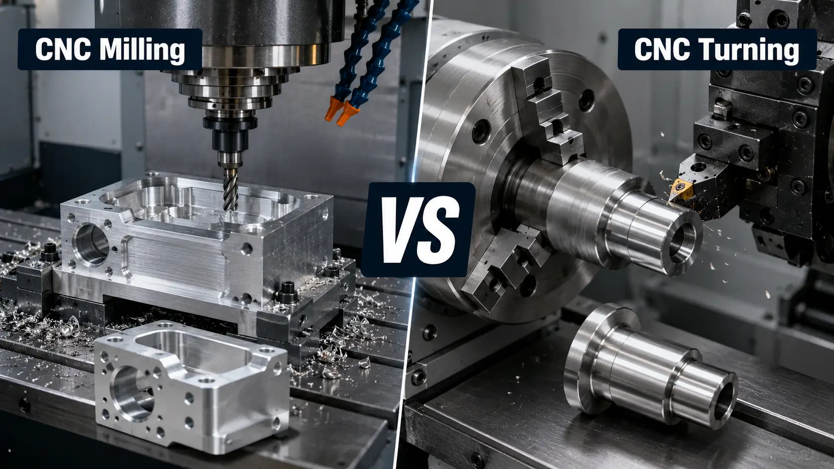
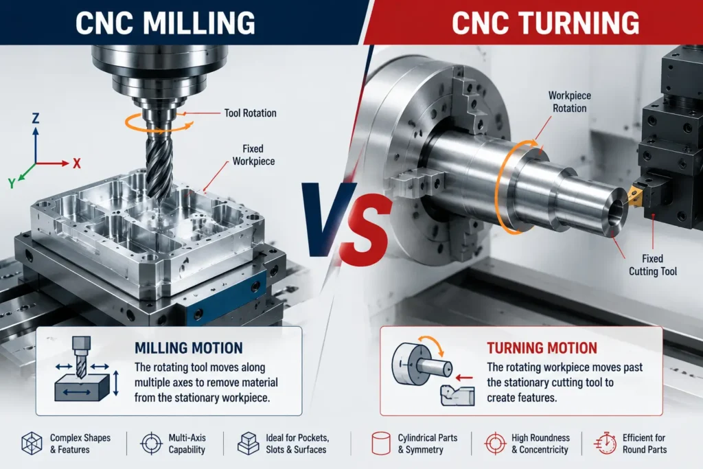
CNC milling removes material with a rotating cutting tool while the workpiece stays fixed in a vise or fixture. Machine motion along X, Y, and Z positions the tool; 4-axis and 5-axis machines add rotary axes to reach angled features without a manual re-fixture.
Because the tool moves and the part doesn’t, milling suits flat faces, pockets, slots, and contoured surfaces. Common operations include face milling, pocket and slot milling, contour milling, and drilling or tapping.
What Is CNC Turning?
CNC turning holds the workpiece in a rotating chuck while a tool feeds into it along and across the centerline. Bar-fed lathes run multiple parts from a single length of stock; many turning centers also carry a tailstock for long parts and a sub-spindle to finish the second end.
Because the part itself rotates, turning naturally produces symmetric features: diameters, bores, tapers, threads. Common operations include facing, OD turning, boring, threading, grooving, and parting off. Features off the centerline, such as a cross-hole, need a milling operation or a lathe with live tooling.
CNC Milling vs CNC Turning at a Glance
| Factor | CNC Milling | CNC Turning |
|---|---|---|
| Workpiece motion | Stationary | Rotates in a chuck |
| Suited geometry | Prismatic, asymmetric, multi-face | Rotationally symmetric |
| Typical stock form | Block, plate | Bar stock, tube |
| Typical general tolerance | ±0.05–0.13 mm | ±0.02–0.05 mm |
| Typical as-machined finish | 0.8–3.2 μm Ra | 0.4–1.6 μm Ra |
| Setup count on complex parts | Higher | Lower |
| Stock utilization | Lower on block-based parts | Higher, bar tracks finished diameter |
CNC Milling vs CNC Turning: Key Differences
Machine Motion and Part Geometry
Milling moves the tool around a fixed part, reaching whatever the current setup allows. A 3-axis machine only reaches what’s visible from above; 4- and 5-axis machines add rotary motion so the tool can reach angled or side features without re-fixturing the part.
Turning rotates the part around one axis, so every feature it produces — a diameter, a bore, a taper — is inherently symmetric around that axis. There’s no equivalent to a 5-axis approach angle here; the part’s own rotation does the work that extra axes do on a mill.
A bracket with flat faces and off-center holes needs milling, because none of its features share a common axis. A shaft with stepped diameters and a shoulder needs turning, because all of its features do. Geometry decides which process applies — not preference, and not which machine happens to be free.
Tooling and Feature Access
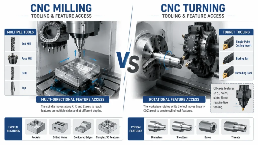
Milling uses end mills, face mills, drills, and taps, held in a magazine and swapped automatically through the program as different features come up. This lets one milling setup move between very different feature types — a pocket, a hole, a contoured edge — without a tool change interrupting the flow.
Turning uses single-point inserts, boring bars, and threading tools, mounted in a turret and indexed into position as the program calls for each cut.
A milling program can reach any feature included in the current setup. A turning program can only reach what’s accessible from the tool’s path relative to the rotating part — an off-axis feature, like a cross-hole, sits outside that reach unless the machine carries live tooling.
Accuracy and Geometric Control
Turning holds diameter, length, and concentricity tolerances efficiently, since the part’s own rotation keeps those features aligned without extra fixturing effort. A shaft with two diameters and a shoulder can hold a tight concentricity call between them in one turning setup.
Milling holds position, flatness, and parallelism between features on different faces, since each one is located directly by the machine’s coordinate system rather than by the part’s own motion. A bracket whose hole pattern must sit precisely relative to a machined edge needs both features cut in the same milling setup — splitting them across setups reintroduces the alignment error a single setup would have avoided.
Surface Finish
Turning typically finishes finer, around 0.4–1.6 μm Ra, because continuous rotational cutting leaves a more uniform surface than milling’s intermittent tool engagement. This is part of why bearing journals and seal diameters are often specified as turned features even on parts that are otherwise milled.
Milled surfaces typically run 0.8–3.2 μm Ra as-machined and can show visible tool-path scallops on contoured or 3-axis-finished surfaces, where a ball-nose cutter leaves a scalloped pattern between passes.
A finer milled finish means either a reduced stepover between passes, which adds cycle time, or a secondary polishing or blasting operation after machining.
Setup and Production Efficiency
A symmetric part on a lathe often finishes in one or two setups, since the chuck holds the part through most or all of the operations, and a sub-spindle can pick it up to finish the second end without manual re-fixturing.
A prismatic part on a mill more often needs several setups to reach features on different faces, and each one adds fixturing time, datum re-referencing, and — on tight-tolerance features — an in-process check before the next operation runs.
This gap in setup count is a main reason turning tends to run faster, and cheaper, per part than milling for geometry that suits either process.
Cost Considerations
Milled parts are priced mainly by setup count and how much material gets removed relative to the starting block. A part cut from a block much larger than its finished shape costs more in both material and machine time to hollow out, and each added setup adds fixed labor that doesn’t shrink with part size.
Turned parts are priced mainly by cycle time and stock utilization, since bar diameter can be picked close to the part’s finished diameter, keeping material removal to a minimum.
A part suited to turning generally costs less than the same part redesigned for milling — less starting material, fewer setups, and a lower machine hourly rate on a standard lathe than on a multi-axis mill.
How to Choose Between CNC Milling, Turning, and Mill-Turn Machining
When Milling Is the Better Fit
Milling fits parts with flat mounting faces, pockets, slots, or features spread across multiple non-symmetric faces — housings, brackets, plates with hole patterns. It’s also the right call whenever a feature’s position matters relative to an edge or another face rather than to a centerline, since milling locates each feature directly by machine coordinates.
Parts still going through design changes also tend toward milling by default, since a revised program is the only cost of a design update — there’s no tooling or fixture investment to lose if a dimension shifts.
When Turning Makes More Sense
Turning makes more sense for parts that are rotationally symmetric along most of their length — shafts, bushings, threaded fittings, flanges — with their functional features concentrated on a single centerline. It’s the more efficient choice as volume rises for this geometry too, since a bar-fed lathe can run parts back to back from one length of stock with little operator intervention between cycles.
If a drawing’s tightest tolerances are concentricity or diameter calls rather than positional calls between faces, that’s a further sign the part belongs on a lathe.
When the Part Needs Both Processes
A rotational body with off-axis features is the clearest case for combining processes — a shaft with a cross-hole, a flange with a bolt pattern, a valve body with a bored passage and flat mounting faces. Trying to force this kind of part onto one process alone usually costs more than splitting the work: milling the whole thing from a block wastes material that turning would have removed efficiently, and turning alone simply can’t reach the off-axis features at all.
The practical question is not whether both processes are needed, but how they get combined — on two separate machines, on a lathe with live tooling, or on a single mill-turn setup.
Separate Machines, Live Tooling, or Mill-Turn?
Moving a part between a lathe and a mill means re-fixturing and re-referencing datums, which adds handling time and an alignment risk. A turning center with live tooling can mill a simple off-axis feature without the part leaving the chuck. A full mill-turn machine handles more extensive off-axis geometry in one setup, at a higher hourly rate than either machine alone.
Questions to Ask Before Selecting a Process
Is the part rotationally symmetric along its full length, or only part of it? This is the first filter — a partial answer usually points toward a combined process.
Are there off-centerline features, and how many? One simple feature may suit live tooling; several, or a contoured one, usually needs a dedicated milling operation.
Which dimensions carry the tightest tolerance — concentric or positional? Concentric calls favor turning in one setup; positional calls between faces favor milling.
Does volume justify a dedicated fixture, bar feeder, or mill-turn program? At low volume, the setup best avoided is the one that costs the most to build.
What stock form is realistically available? A process that doesn’t match an available bar, plate, or tube size adds material cost regardless of which one is chosen.
Examples of Milled, Turned, and Combined-Machining Parts
The difference between milling and turning becomes easier to understand when applied to actual part geometry. The following examples show where each process is commonly used, although the final route may vary with tolerances, feature relationships, production quantity, and available equipment.
| CNC-Milled Parts | CNC-Turned Parts | Parts That May Require Both |
|---|---|---|
| Aerospace brackets with pockets and mounting holes | Drive shafts with stepped diameters | Sensor housings with cylindrical bodies and mounting flats |
| Equipment plates with precise hole patterns | Pins with controlled diameters | Valve bodies with side ports and internal bores |
| Medical equipment housings with thin walls | Bushings and sleeves | Threaded connectors with wrench flats |
| Electronic enclosures with internal cavities | Spacers and standoffs | Shafts with milled keyways |
| Fluid manifolds with intersecting channels | Nozzles with tapered profiles | Cylindrical housings with bolt patterns |
| Automation fixtures with multiple datum faces | Threaded fittings | Rotational parts with cross-holes or slots |
The same category of part can sometimes be manufactured in more than one way. The drawing, tolerance scheme, quantity, and required setup strategy ultimately determine the most suitable route.
Advantages and Limitations of CNC Milling and Turning
| Advantages | Limitations | |
|---|---|---|
| CNC Milling | Reaches non-symmetric geometry and 3D contours | More setups on complex parts, lower stock utilization |
| CNC Turning | Fast cycle time, high stock utilization, strong concentricity | Limited to features on the rotating part’s axis |
Choosing the Right CNC Machining Process
Follow the part’s geometry, not familiarity with one process. A mostly symmetric part should default to turning, with milling or live tooling added only for the features that need it. A part without a dominant rotational axis should default to milling, with setup count kept as low as the design allows. A part with both should be checked against live tooling or mill-turn before splitting it across two separate machines.
Why Choose ZH Prototyping for CNC Milling & Turning
ZH Prototyping is an experienced CNC machining manufacturer specializing in custom CNC milling and CNC turning services for precision metal components. Our engineering team reviews each CAD drawing to determine the most suitable machining process, selecting milling, turning, or mill-turn operations based on part geometry, tolerance requirements, and production volume. We support a wide range of metal alloys for prototype development and production manufacturing.
We provide transparent pricing, free DFM manufacturability reviews, and consistent dimensional control for precision-machined parts. Send your CAD files to our engineering team for DFM feedback and a detailed quotation.
Conclusion
Milling and turning differ in one basic way: which part moves. This difference affects part geometry, tolerance, surface finish, setup requirements, and overall cost. Turning is ideal for rotationally symmetric parts and is usually faster and more cost-effective when the geometry fits the process. Milling is suitable for more complex features, including flat faces, off-center features, and multi-face parts that cannot be produced with a single-axis turning operation.
In practice, most parts are not a perfect match for only one process. The key is identifying which features are rotationally symmetric and which require additional machining operations. For some components, combining processes through live tooling or mill-turn machining can reduce setup time and overall cost compared with moving the part between multiple machines.




