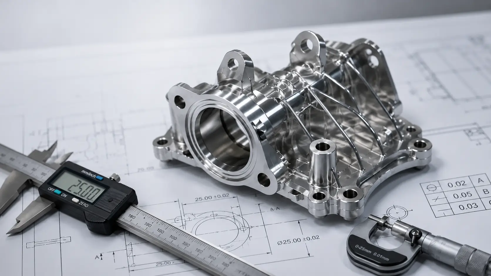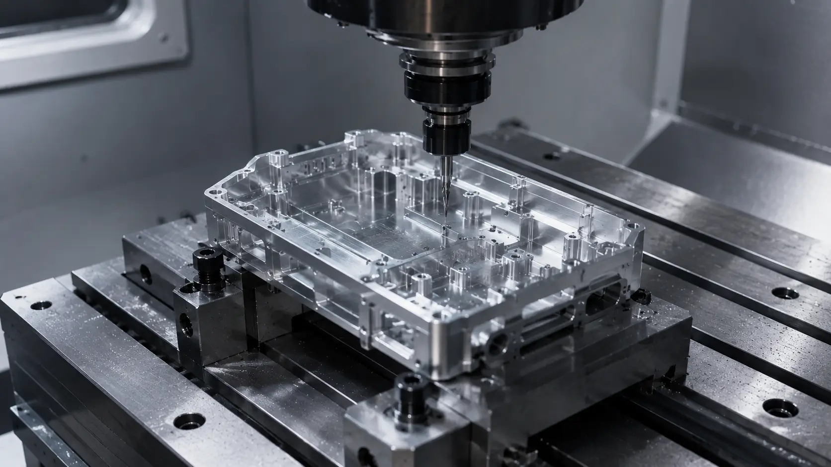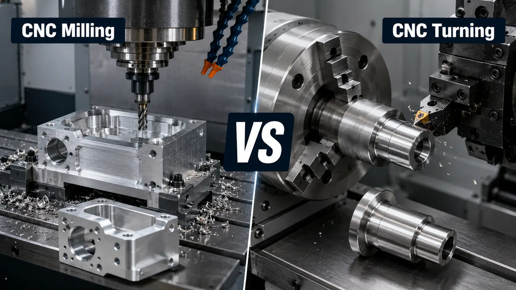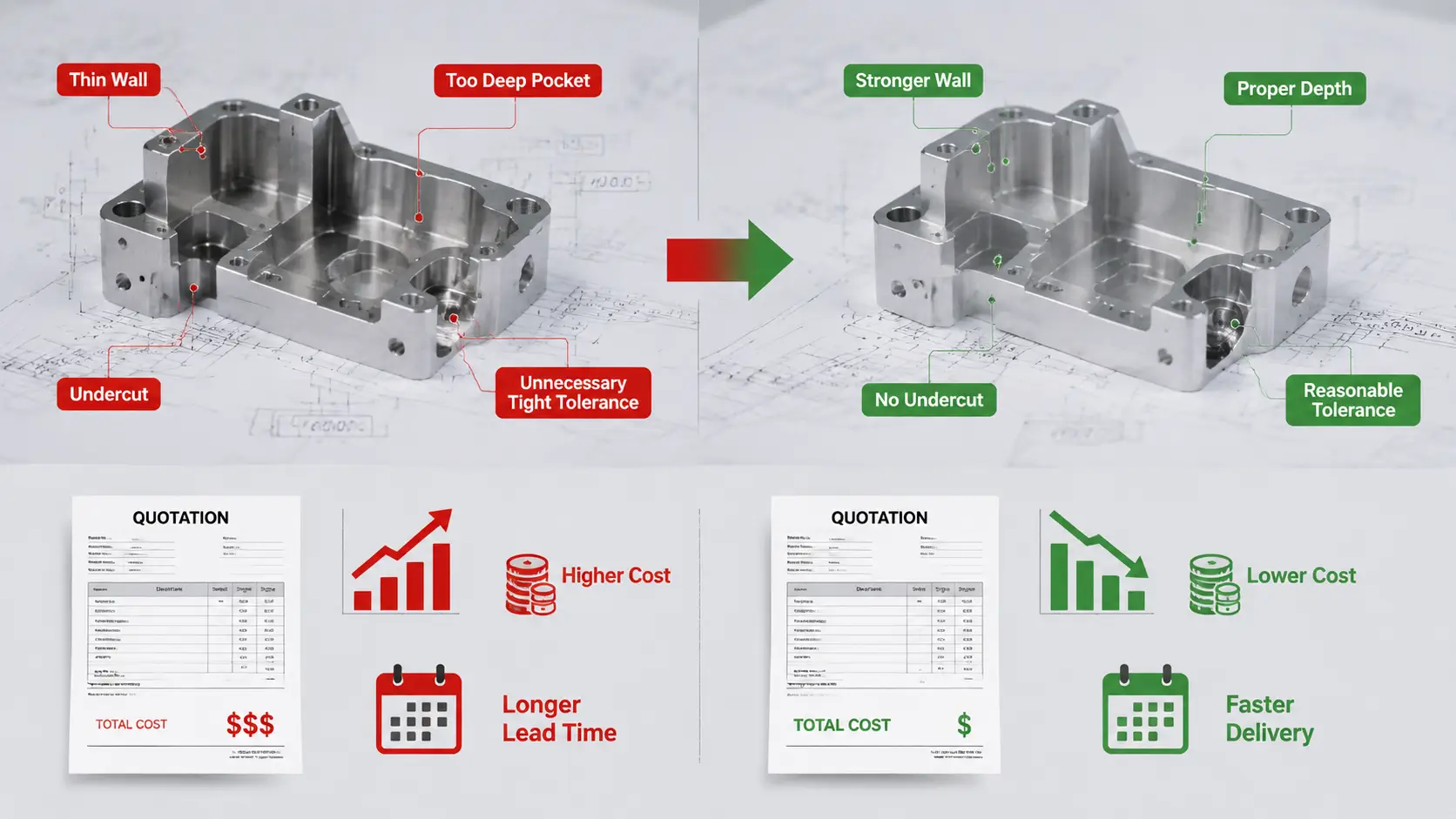
A pocket that is slightly too deep. A tolerance tighter than the feature actually needs. An undercut that forces an additional setup. None of these necessarily look like mistakes on the drawing. They simply show up later as longer machining time, additional tooling, more inspection, or a higher quote.
That is exactly what DFM is built to catch. It is not a machine shop finding fault with your design. It is a review of how geometry, tolerances, material, tool access, and setup requirements affect the way the part must be manufactured. This guide explains what DFM means for CNC machining, how design decisions influence cost, and which changes can make a part easier to manufacture without changing its intended function.
What Is DFM in CNC Machining?
DFM stands for Design for Manufacturability. In CNC machining, it means reviewing a part before production to determine whether it can be manufactured efficiently and consistently with practical tooling, workholding, setups, machining processes, and inspection methods.
A part can be technically machinable and still be unnecessarily expensive to produce. A deep pocket may be reachable, for example, but only with a long-overhang cutter and slower cutting parameters. A tight tolerance may be achievable, but it may require additional finishing operations and inspection that the feature does not actually need.
That distinction is important. CNC machining DFM is not about redesigning a part simply to make the machine shop’s job easier. It is about identifying manufacturing difficulty that does not contribute to the part’s function.
A useful DFM review typically considers:
- Wall thickness and part rigidity
- Tolerance requirements versus functional needs
- Hole depth, diameter, and accessibility
- Internal corner radii
- Tool and holder access
- Features requiring additional setups
- Specialized tooling requirements
- Inspection and measurement requirements
DFM is most useful before the drawing and manufacturing assumptions are fully locked. Changing a non-critical feature in CAD takes very little effort. Discovering the same problem after material has been cut may mean additional machining, scrap, rework, or a delayed delivery.
How DFM Affects CNC Machining Cost
Every CNC machining project has a few fundamental cost drivers: machine time, setup time, tooling, inspection, and process risk. Design decisions influence all of them.
Machine time is the most obvious. Deep pockets, small internal radii, difficult surfaces, and features with limited access may require smaller tools, longer toolpaths, reduced cutting parameters, or additional finishing passes.
Setup count matters just as much. If features need to be machined from several directions, the part may need to be removed, repositioned, indicated, and machined again. Every additional setup adds handling and process time while creating another opportunity for alignment variation.
Tooling can also change quickly with geometry. A standard end mill or drill is inexpensive and readily available. Long-reach cutters, very small tools, undercut cutters, or specialized thread tooling may increase both machining time and tooling cost.
Inspection is another cost that is easy to overlook during design. A tighter tolerance does not only affect how the feature is machined. It may also require additional measurements, different inspection equipment, more frequent verification, or closer control of the machining process.
Finally, some designs carry more process risk. Thin sections may deflect, difficult workholding may allow movement during machining, and long tools may be more susceptible to vibration. These risks can lead to slower machining strategies, additional inspection, or a higher probability of scrap and rework.
For custom CNC machining, relatively small changes in geometry or tolerance can therefore have a much larger effect on cost than the CAD model alone suggests.
CNC Machining DFM Guidelines That Reduce Cost
The design decisions below appear in many CNC machining projects. The goal is not to simplify every part indiscriminately, but to understand which features create manufacturing difficulty and whether that difficulty is functionally necessary.
Wall Thickness and Part Rigidity
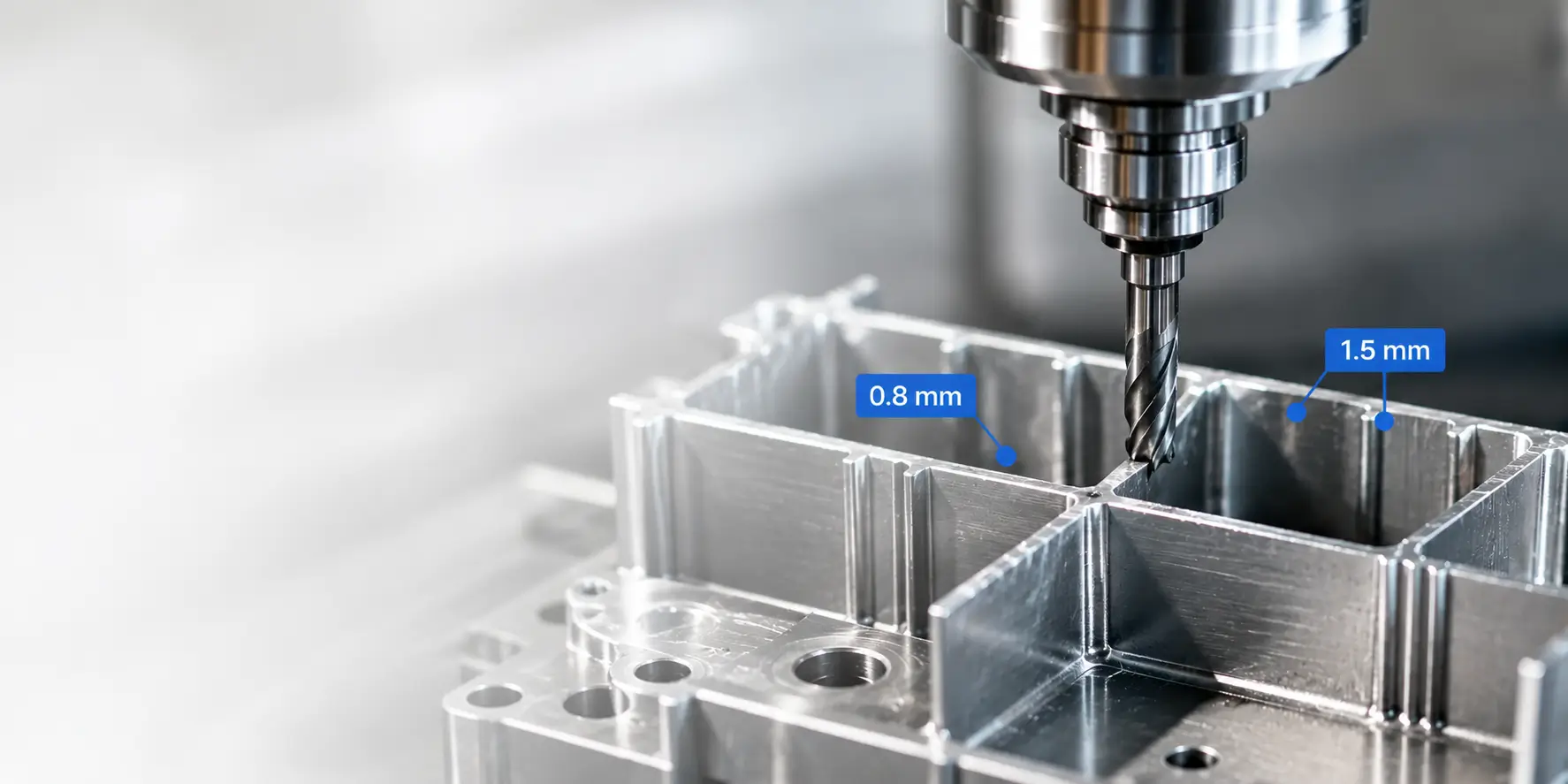
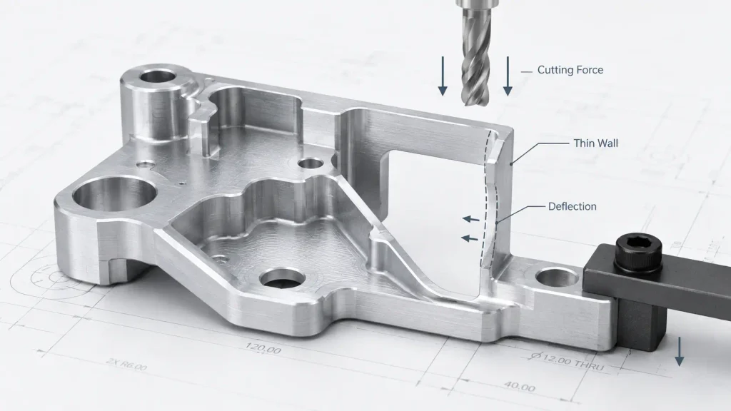
Thin walls lose rigidity as surrounding material is removed. Under cutting forces, the wall can deflect away from the tool, causing dimensional variation. Low stiffness can also make the part more susceptible to vibration or chatter, which may affect surface finish and machining stability.
Workholding adds another variable. A thin section can distort under clamping force and then move again after the fixture is released. This is one reason a dimension measured while the part is clamped may not always represent its final free-state condition.
There is no single minimum wall thickness that applies to every CNC machined part. Manufacturability depends on the wall height, unsupported span, material stiffness, geometry, tolerance, workholding strategy, and machining sequence.
Where the design allows it, increasing wall stiffness gives the machinist more room to use productive cutting parameters. When thin walls are functionally necessary, the machining process may instead require lighter cuts, staged material removal, additional finishing passes, or inspection after unclamping.
The DFM question is therefore not simply “Is this wall thick enough?” It is whether the wall has enough rigidity to remain stable through machining and inspection while still meeting the design requirement.
Internal Corner Radii
CNC end mills are round, so a conventional milling cutter cannot produce a perfectly sharp internal corner.
The more important DFM issue is the relationship between corner radius, cutter diameter, pocket depth, and tool rigidity.
A very small internal radius can force the manufacturer to use a smaller-diameter cutter. In a deep pocket, that cutter may also require greater tool overhang. Both conditions reduce rigidity and can increase tool deflection, machining time, and the number of passes required.
Where function allows it, use the largest practical internal corner radius rather than specifying a radius simply because it can be modeled in CAD. A larger radius gives the manufacturer more freedom to use a larger and more rigid cutter.
This becomes increasingly important as pocket depth increases.
A sharp internal corner may still be required for certain assemblies or mating features. In those cases, another process such as EDM may be considered, but it introduces additional operations, cost, and lead time.
Hole Depth, Diameter, and Tolerance
Deep, narrow holes are a common source of unexpected machining difficulty.
As the depth-to-diameter ratio increases, chip evacuation becomes more difficult, tool rigidity decreases, and drilling may require peck cycles, reduced cutting parameters, or specialized tooling and coolant strategies. These changes increase cycle time and can raise the risk of tool failure.
Hole diameter matters as well. Standard drill sizes are generally easier and less expensive to produce because suitable tooling is readily available. A non-standard diameter does not automatically require a custom tool, but it may require interpolation, boring, reaming, or another secondary operation.
Tolerance and function are just as important as nominal diameter.
A clearance hole may only require drilling. A locating hole may require drilling followed by reaming. A precision bore may require boring or circular interpolation followed by inspection.
Two holes with the same nominal diameter can therefore have very different manufacturing costs depending on their tolerance, surface finish, position requirement, and function in the assembly.
When reviewing a hole for DFM, consider depth, diameter, tolerance, access, and function together rather than treating the nominal size alone as the machining requirement.
Threads and Tapped Holes
Threads are another feature where small drawing decisions can introduce unnecessary tooling or machining time.
Standard thread sizes and pitches can usually be produced with readily available taps or thread mills. An uncommon thread form or pitch may require specialized tooling that is used for only one feature on the entire part.
Thread depth also deserves attention, particularly in blind holes. Specifying considerably more threaded depth than the joint actually requires can increase machining time and make chip evacuation or tool clearance more difficult.
At the same time, thread engagement should not be reduced according to a universal rule. The required engagement depends on the parent material, fastener strength, thread size, applied load, and overall joint design. Softer materials may require greater engagement than stronger materials.
The DFM goal is therefore to provide enough engagement for the mechanical requirement without adding unnecessary thread depth simply because space is available in the CAD model.
Undercuts and Tool Accessibility
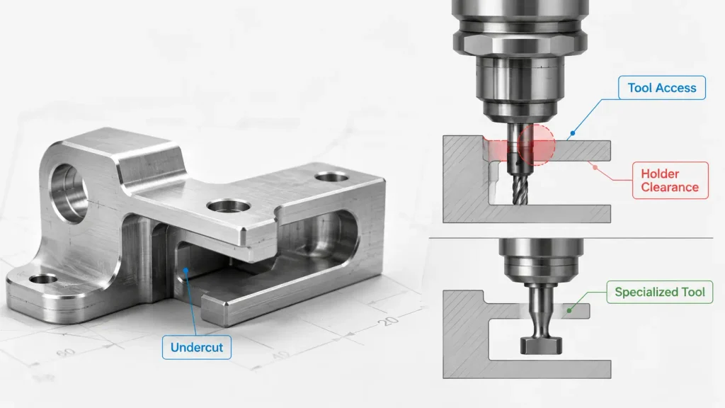
Undercuts are difficult because the cutting edge must physically reach geometry that is partially blocked by surrounding material.
A standard 3-axis end mill can only approach a feature from certain directions. An undercut may therefore require a T-slot cutter, lollipop cutter, dovetail cutter, another specialized tool, or an additional setup.
Tool access should also be considered beyond the cutting edge itself. The cutter may technically reach the feature while the tool shank or holder collides with surrounding geometry.
Where possible, designing undercuts around commonly available tool geometries can reduce specialized tooling and additional setups.
5-axis CNC machining can improve access to angled or difficult-to-reach features and may reduce repositioning. It does not, however, eliminate every undercut problem. A true undercut may still require dedicated tooling if surrounding geometry prevents a conventional cutter from reaching the surface.
The useful DFM question is not simply whether the machine has enough axes. It is whether the cutter, shank, and holder can reach the required surface with sufficient clearance and rigidity.
Minimize Unnecessary Setups
Setup count has a direct effect on CNC machining cost, but its influence is easy to miss during design.
A feature that requires the part to be removed from the fixture, rotated, re-indicated, and machined from another direction adds more than cutting time. It may also require additional workholding, operator handling, datum transfer, alignment, and inspection.
Each repositioning can introduce another source of variation between features produced in different setups.
This does not mean every part should be designed for a single setup. Many components genuinely require machining from several directions. The DFM opportunity exists when the orientation of a non-critical feature can be changed without affecting function.
Where the design allows it, grouping features around common machining directions or common datums can reduce repositioning and simplify process planning.
Reducing one unnecessary setup can sometimes have a greater effect on cost than reducing several minutes of cutting time.
Apply Tight Tolerances Only Where Function Requires Them
Tolerances are one of the most common drivers of CNC machining cost, particularly when tight requirements are applied uniformly across a drawing.
Tight tolerances are not inherently a problem. Bearing fits, locating features, sealing surfaces, precision bores, and mating interfaces may genuinely require close dimensional control.
The cost increases when the same level of precision is applied to features that do not affect fit, function, alignment, or performance.
A tighter tolerance may require additional finishing passes, more stable workholding, tool compensation, closer process control, and more extensive inspection. Depending on the feature, it may also require different measurement equipment or increase the risk of rework if the process begins to drift.
A part with one critical mating surface and twenty non-critical dimensions does not necessarily need twenty-one tight tolerances. The drawing should identify which dimensions control the function of the part and allow practical general tolerances elsewhere.
ISO 2768-m general tolerances can be useful for dimensions that do not require individual tolerance callouts, while tighter feature-specific tolerances should be reserved for dimensions that genuinely require additional control.
The principle is simple: specify precision according to function, not habit.
Simplify Non-Functional Geometry
Not every complex feature should be removed simply because it takes longer to machine.
A curved surface may control fluid flow. A fillet may reduce stress concentration. A contour may provide assembly clearance or satisfy an appearance requirement. These are functional features, even if they increase machining time.
The better DFM target is geometry that adds machining complexity without contributing to the part’s intended performance.
Decorative contours, unnecessary blended surfaces, or features carried over from another manufacturing process can sometimes add toolpaths and setups without adding functional value.
This is particularly common when a part originally designed for casting or additive manufacturing is later converted to CNC machining. Geometry that was inexpensive in the original process may be inefficient to produce subtractively.
The question worth asking is not “Can this shape be simplified?” but “Does this geometry contribute to fit, load, assembly, performance, or an intentional appearance requirement?”
If the answer is no, simplifying it may reduce machining time without compromising the part.
Part Marking and Traceability
Part marking is usually a secondary consideration in CNC DFM, but planning it early can avoid unnecessary handling later.
If a part requires a part number, revision, serial number, date code, or other traceability information, leave an accessible surface suitable for the selected marking method. Laser engraving is commonly used for CNC machined parts, although the appropriate method depends on material, finish, depth requirement, and industry requirements.
Planning the marking location during design is particularly useful for automotive, aerospace, and other traceability-sensitive applications where identification forms part of the quality process.
Common CNC Machining DFM Mistakes
Most expensive-to-machine designs are not badly engineered. More often, a few reasonable design decisions create manufacturing consequences that were not obvious when the CAD model was created.
Copying tolerances from a reference part. It is common to reuse tolerances from an existing component or drawing template without reconsidering whether the new feature serves the same function. A tolerance that was necessary on one design does not automatically belong on another.
Treating all materials the same. Aluminum, stainless steel, titanium, and other engineering materials behave differently during machining. Tool wear, heat generation, cutting forces, chip control, and achievable machining strategies can change when the material changes. Checking material-specific machining characteristics before the design is frozen can prevent a geometry that was practical in one material from becoming unnecessarily expensive in another.
Involving the CNC machining supplier too late. DFM is most useful while non-critical design decisions can still change. Once the drawing has been fully approved and released, an obvious manufacturing improvement may no longer be practical because changing it would trigger another internal design cycle. Bringing the CNC machining supplier into the discussion earlier gives both sides more room to identify cost drivers before they become fixed requirements.
Designing around a different manufacturing process. Thin ribs, organic surfaces, deep internal cavities, draft features, and other geometry may make sense for casting or additive manufacturing but translate poorly to a subtractive machining process. A part adapted from another process should be reviewed as a machining problem rather than assuming the original geometry remains equally efficient.
When to Request a CNC Machining DFM Review
A DFM review is most valuable before manufacturing decisions become difficult to change.
That may be before releasing the final drawing, before machining the first prototype, after a major geometry revision, or when a quote comes back significantly higher than expected. It can also be useful before moving from prototype quantities into repeat production, where a few additional minutes of machining time can become much more significant across multiple parts.
Parts with thin walls, deep cavities, difficult tool access, multiple machining directions, tight tolerances, or demanding inspection requirements are particularly good candidates for an early review.
The review does not need to change the entire design. Often, the useful output is simply identifying which features are driving additional setups, specialized tooling, slower machining, or inspection effort.
For a practical review, provide both the 3D CAD model and the 2D drawing when available. The CAD model defines geometry and helps evaluate machining access, while the drawing communicates tolerances, GD&T, threads, surface finish, and other requirements that cannot be inferred reliably from nominal geometry alone.
ZH Prototyping provides a free DFM review before production. Upload your CAD files to have the design reviewed for machining access, setups, tolerances, and potential cost drivers before the manufacturing process is finalized.
Conclusion
CNC machining cost is often determined long before material reaches the machine.
DFM does not mean removing every difficult feature or loosening every tolerance. A difficult feature that performs an important mechanical function may be worth the machining cost. The opportunity is to remove manufacturing difficulty that does not contribute to that function.
Better tool access, practical internal radii, appropriate wall rigidity, fewer unnecessary setups, and tolerances tied to actual functional requirements can make the machining process more stable and efficient without changing what the part is designed to do.
For custom CNC parts, these decisions are easiest to change before the drawing is released and the process is locked. That is where DFM has the greatest value: not making the design simpler for its own sake, but making sure manufacturing complexity is spent only where the part actually needs it.