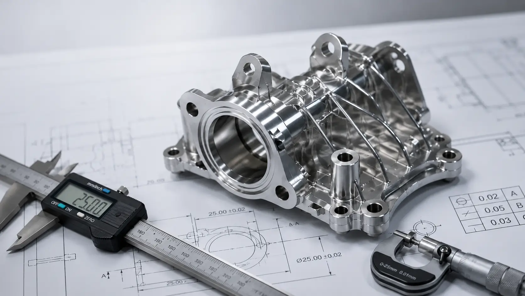
Tighter tolerances are not automatically better. A bearing bore, locating hole, or mating surface may need close dimensional control, while an exterior edge or non-critical pocket usually does not. Applying the same tight tolerance across an entire drawing adds machining and inspection work without improving part function, and it shows up directly in the quote.
This guide explains what CNC machining tolerances mean in practice, what affects achievable accuracy, how to specify tolerances on a drawing, and what procurement teams should confirm before sourcing tight-tolerance parts.
What Are CNC Machining Tolerances?
CNC machining tolerances define how much a finished part is allowed to vary from the dimensions shown on the engineering drawing.
It is nearly impossible to produce every part at the exact target size. Cutting forces, tool wear, machine condition, material movement, and inspection method all introduce small variations. A tolerance tells the manufacturer how much variation is acceptable while the part still performs its function.
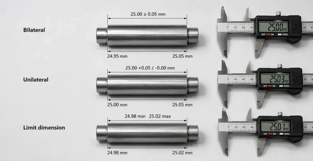
For example, if a drawing specifies 25.00 ±0.05 mm, the finished feature can measure anywhere between 24.95 mm and 25.05 mm and still meet the requirement.
Common Types of CNC Machining Tolerances
Three tolerance formats show up most often on machining drawings.
Bilateral tolerance: the dimension can vary in both directions, such as 25.00 ±0.05 mm.
Unilateral tolerance: variation is allowed mainly in one direction, such as 25.00 +0.02 / -0.00 mm.
Limit dimensions: the drawing lists the minimum and maximum acceptable size directly, such as 24.98 to 25.02 mm.
Not every feature needs the same tolerance format. Locating holes, bearing seats, and mating surfaces often need tighter control, while non-critical pockets and exterior surfaces work fine with a wider general tolerance. The tolerance is not just a statement of how accurately a machine can cut. It defines the accuracy the part actually needs to function.
How to Interpret Standard CNC Machining Tolerances
Not every dimension needs an individual tolerance callout. Non-critical dimensions can reference the ISO 2768 general tolerance standard instead, so a note such as “unless otherwise specified, tolerances per ISO 2768-m” tells the manufacturer exactly how to treat the rest of the drawing.
| Nominal Size Range (mm) | f (Fine) | m (Medium) | c (Coarse) | v (Very Coarse) |
|---|---|---|---|---|
| 0.5-3 | ±0.05 | ±0.1 | ±0.2 | – |
| 3-6 | ±0.05 | ±0.1 | ±0.3 | ±0.5 |
| 6-30 | ±0.1 | ±0.2 | ±0.5 | ±1.0 |
| 30-120 | ±0.15 | ±0.3 | ±0.8 | ±1.5 |
| 120-400 | ±0.2 | ±0.5 | ±1.2 | ±2.5 |
| 400-1000 | ±0.3 | ±0.8 | ±2.0 | ±4.0 |
Most shops default to the m (medium) class. On a typical part, the majority of dimensions can simply follow this table, leaving only a handful of critical features that need a specific tolerance called out.
What Tolerances Can CNC Machining Achieve?
There is no single tolerance that applies to every CNC machined part. Achievable accuracy depends on the feature, part geometry, material, workholding, and inspection method.
For most non-critical dimensions, a general tolerance around ±0.05 mm is appropriate. Tighter tolerances, down to ±0.01 mm, can be achieved on selected critical features when geometry and process allow it.
| Tolerance Level | Typical Application | Manufacturing Consideration |
|---|---|---|
| General tolerance | Overall dimensions, pockets, non-critical features | Standard machining and inspection |
| Precision tolerance | Mating features, locating dimensions, critical diameters | Tighter process and inspection control |
| Tight tolerance | Bearing fits, precision bores, critical interfaces | Additional machining and verification steps |
A tighter tolerance should be applied only where part function requires it. A bearing bore may need close diameter control, while the outside length of the same housing may work fine with a wider general tolerance.
Machine Accuracy Is Not Production Tolerance
A CNC machine’s positioning accuracy does not directly equal the tolerance that can be guaranteed on a finished part.
The final result is also shaped by tool deflection, cutting forces, workholding, material movement, temperature, setup changes, tool wear, and measurement conditions. A machine can have very small positioning error and still produce a thin wall or unsupported feature that shifts during cutting.
For this reason, tolerance capability should always be evaluated at the feature and part level, not from a machine’s spec sheet alone.
Where Are Tight Tolerances Necessary?
Bearing bores and shaft fits directly affect how smoothly a part rotates. Sealing grooves need close control to seal properly without over-compressing. Dowel hole position determines assembly alignment. Datum surfaces in stacked assemblies carry that accuracy through the whole build.
Exterior surfaces, non-mating mounting holes, wire pass-through holes, and fastener clearance holes that don’t carry a precision fit can all run on the ISO 2768 general tolerance. Tightening these adds cost without adding function.
Dimensional tolerances alone don’t always describe how features need to relate to each other. Bolt pattern position, mounting surface flatness, and shaft runout are usually better controlled with geometric dimensioning and tolerancing (GD&T), such as position, flatness, perpendicularity, or runout callouts. Dimensional tolerance controls size. GD&T controls how features relate to each other, and drawings that mix both correctly leave far less room for misinterpretation.
What Affects CNC Machining Tolerance Capability and Cost?
In tight tolerance CNC machining, the same dimensional requirement can be routine on one part and expensive on another.
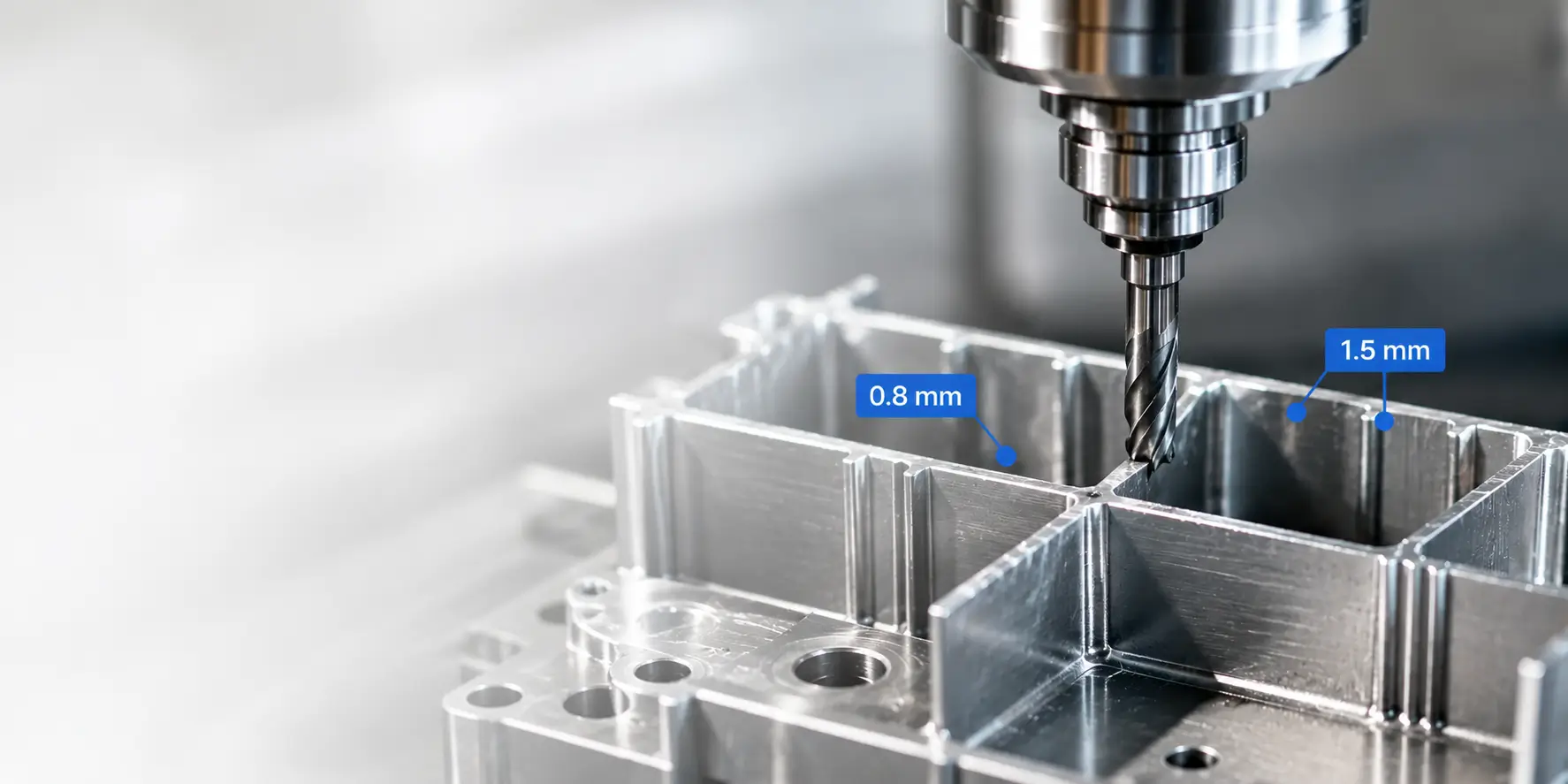
Material and part geometry. Aluminum machines with lower cutting forces and less distortion, so it holds tight tolerances more easily. Stainless steel and titanium require higher cutting forces and generate more heat, which increases tool deflection risk if the process isn’t controlled. Thin-wall CNC machining is especially sensitive to cutting force and clamping pressure, particularly around deep pockets and unsupported sections, where the part can shift slightly after internal stress releases.
Tooling and tool access. Longer tool overhang into a deep cavity or narrow slot increases vibration and deflection, so dimensional control gets harder. These features often need a dedicated machining strategy rather than the standard toolpath used elsewhere on the part.
Workholding and number of setups. A part needs to be held firmly enough to resist cutting forces without being distorted by the fixture itself, which matters most on thin or flexible parts. Features completed in a single setup are easier to hold; every additional setup introduces a new source of positional error between features.
Temperature and inspection. Machining generates heat, so a part measured right off the machine can read slightly differently once it cools to a stable temperature. Inspection method also has to match the tolerance: a caliper is fine for general dimensions, a bore gauge or pin gauge for precision holes, and a CMM for position, flatness, or other GD&T callouts.
CNC machining cost also scales with how many features carry a tight tolerance. Holding one critical bore to a close tolerance is a very different job than applying the same requirement across dozens of dimensions on the same part.
How to Specify CNC Machining Tolerances
A tolerance should describe what the part needs to do, not simply how accurately a machine can cut it.
Start with function and fit. Identify what role each dimension plays in the assembly: a mating surface, a locating feature, or a purely cosmetic dimension.
Choose the right tolerance format. Use unilateral tolerances where direction matters, bilateral for general dimensions, and limit dimensions where an inspection report will reference the values directly.
Apply tight tolerances only where function requires them. Tightening a dimension that doesn’t affect fit or performance adds cost without adding value.
Let general tolerances cover the rest. A single ISO 2768-m note keeps the drawing clean and avoids over-specifying every dimension individually.
Define inspection requirements up front. Flag which features need a CMM report so there’s no ambiguity at final inspection.
Example: Tolerancing an Aluminum Housing
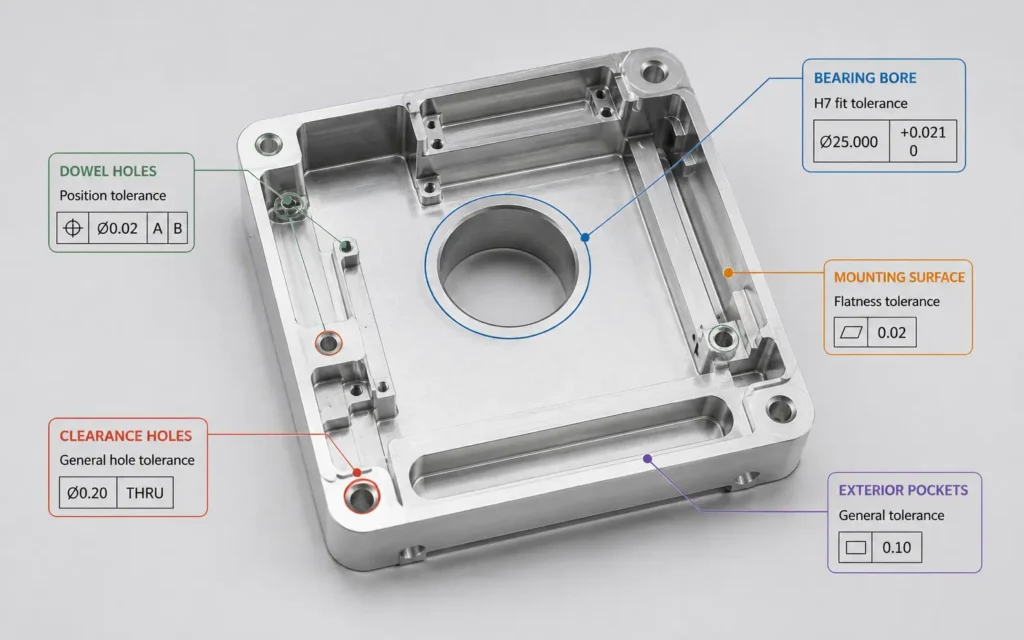
Consider a 6061 aluminum equipment housing with a bearing bore, dowel holes, a mounting surface, clearance holes, and several exterior pockets. Not every feature needs the same tolerance treatment.
| Feature | Recommended Tolerance Approach | Functional Reason |
|---|---|---|
| Overall dimensions | General tolerance | Defines overall part size |
| Bearing bore | H7 or specified fit | Controls bearing fit |
| Dowel holes | Position tolerance | Controls locating accuracy |
| Mounting surface | Flatness | Controls seating and assembly |
| Clearance holes | General hole tolerance | Allows fastener clearance |
| Exterior pockets | General tolerance | Usually non-critical to function |
Specifying every feature at ±0.01 mm would add finishing passes, tighter setup control, and more inspection without any functional benefit. Concentrating precision on the features that affect fit, location, and assembly keeps the drawing clear and gives the manufacturer flexibility to run an efficient process on everything else.
What Procurement Teams Should Confirm Before Sourcing Tight-Tolerance Parts
Engineers set the tolerance, but procurement is usually the one comparing precision CNC machining services and choosing a supplier, so it helps to know what’s actually driving the price difference between bids.
Ask which specific features carry the tight tolerance and why, not just what the overall drawing requires. A supplier quoting the same part at a lower price may simply be planning to hold general tolerances on features where a competitor is over-quoting precision work that isn’t needed.
Confirm what inspection method and documentation come with the quote. A CMM report for GD&T features is a different cost and lead time than a standard dimensional checklist, and this should be spelled out before the PO is placed, not discovered at final inspection.
Ask how tolerance requirements affect lead time, not just price. Tight-tolerance features often add finishing passes and dedicated inspection steps that extend the schedule even when the piece price looks similar across quotes.
Engineering Review for CNC Machining Tolerances
Standard features can often be produced around ±0.05 mm, while selected critical features may require tolerances down to ±0.01 mm when part geometry, material, setup, and inspection conditions allow it.
As a CNC machining supplier, ZH Precision reviews tolerance requirements feature by feature rather than applying the same level of precision across an entire drawing. The engineering review considers material, geometry, feature size, workholding, inspection method, and production requirements together before the machining process is finalized.
Reviewing these requirements before production helps identify where tight tolerances are functionally necessary and where wider general tolerances can reduce machining and inspection complexity without affecting part performance.
Conclusion
CNC machining tolerances should be based on part function rather than applied uniformly across a drawing. General tolerances are sufficient for many dimensions, while bearing fits, locating features, sealing surfaces, and critical interfaces may require tighter dimensional or GD&T control.
The most practical drawing separates these requirements clearly. Doing so gives the machining process enough flexibility for non-critical features while concentrating tighter process and inspection control where the part actually needs it.
FAQ
A common general tolerance for CNC machined parts is around ±0.05 mm. Tighter tolerances, such as ±0.01 mm, may be achievable on selected critical features depending on the material, geometry, machining setup, and inspection method.
Yes. A ±0.01 mm tolerance can be achievable on selected critical dimensions, but it should be evaluated based on feature size, geometry, tool access, workholding, and inspection requirements. Applying this tolerance unnecessarily across an entire part can increase machining and inspection costs.
Yes. Processes such as anodizing and plating add or alter surface thickness and can affect final dimensions. Tight-tolerance features should account for the finishing process during machining and may need to be inspected again after finishing.