

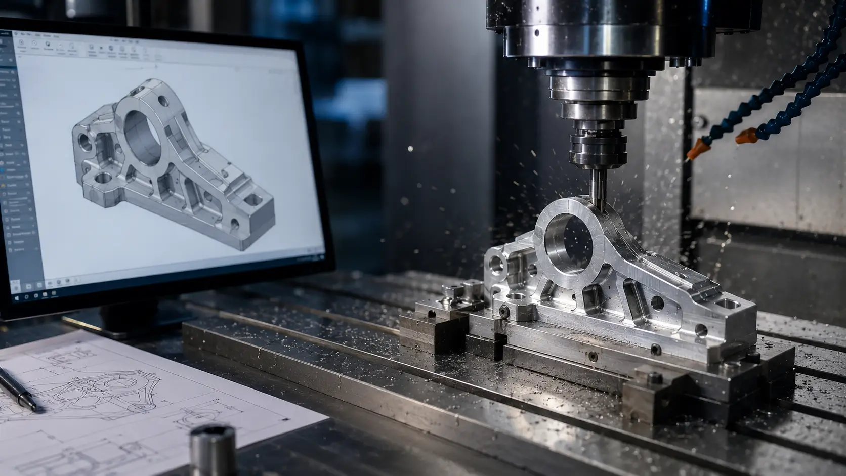
CNC prototyping provides a practical way to make that transition. It works especially well when dimensional accuracy, functional materials, and machined features matter.
Unlike processes that require dedicated production tooling, CNC machining cuts prototypes directly from solid metal or engineering plastic stock. Engineers can use these parts to evaluate geometry, fit, surface condition, and material-dependent performance before choosing a final production process.
This guide explains what CNC prototyping is, when to use it, how it compares with 3D printing, and how the process works. It also covers common materials, tolerances, design considerations, and supplier selection.
What Is CNC Prototyping?
CNC prototyping is a subtractive manufacturing process. Computer-controlled cutting tools remove material from solid stock to produce a physical part from a digital CAD model.
CNC milling handles pockets, holes, slots, flat surfaces, and complex multi-sided geometry. CNC turning works well for cylindrical parts such as shafts, bushings, pins, and threaded components.
The machining process can reproduce the intended geometry within specified tolerances. Engineers can also choose the same material grade and condition planned for production. This makes functional testing more representative than using a substitute material.
CNC prototyping therefore supports more than appearance checks. Engineers can use machined prototypes to verify assembly, mechanical performance, dimensions, manufacturability, and surface finish before moving the design forward.
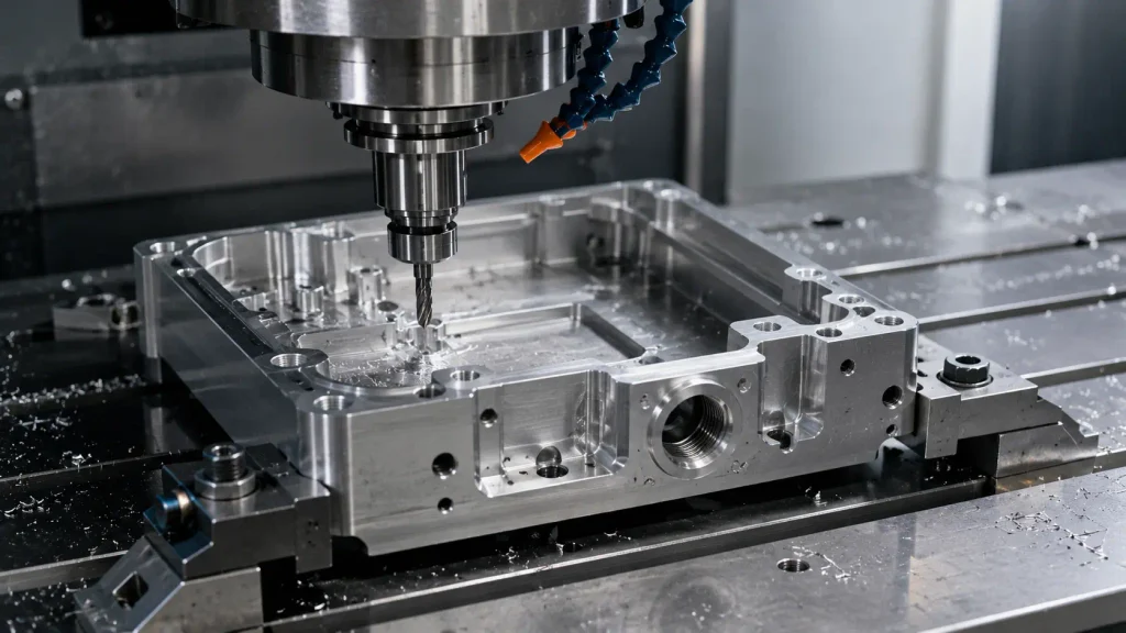
CNC Prototyping vs 3D Printing
CNC machining and 3D printing both support product development, but they solve different problems.
3D printing often works well during early design stages. It can create complex geometry quickly without the tool-access limitations of machining. Engineers commonly use it for concept models, packaging studies, ergonomic evaluation, and basic assembly checks.
CNC prototyping becomes more useful when the test depends on production-representative materials or controlled machined features. Examples include threads, bearing interfaces, sealing surfaces, bores, and precision mating features.
The comparison also depends on the additive process. FDM, SLA, SLS, MJF, and metal additive manufacturing offer very different capabilities. Engineers should not treat all 3D printing processes as having the same strength, accuracy, or material options.
| CNC Prototyping | 3D Printing | |
|---|---|---|
| Manufacturing method | Removes material from solid stock | Builds material layer by layer |
| Materials | Production metals and engineering plastics | Varies by printing process |
| Dimensional control | Well suited to controlled machined features | Depends on process, material, and geometry |
| Surface finish | Machined surfaces with finishing options | Often needs process-specific post-processing |
| Geometry | Limited by cutting-tool access | Strong for complex internal geometry |
| Best suited to | Functional, fit, assembly, and material testing | Concept development and rapid geometry validation |
Neither process is automatically better.
A printed model may be enough when the goal is to check overall shape or assembly space. CNC machining becomes more valuable when the test involves a bearing bore, sealing face, threaded connection, or production alloy.
For a broader explanation of the manufacturing technology, see What Is CNC Machining?
Why Engineers Use CNC Prototyping
The main advantage of CNC prototyping is not simply the physical part itself. The prototype can answer engineering questions that CAD alone cannot resolve.
Production-Representative Materials
Engineers can select the same alloy or engineering plastic planned for the finished component.
For example, a team developing a 6061-T6 aluminum part can prototype it in 6061-T6. This helps them evaluate stiffness, weight, thermal behavior, thread performance, and mechanical loading more realistically.
However, the same alloy does not always guarantee identical performance. Heat treatment, stock form, grain direction, machining history, and surface treatment can influence the final result.
The goal is to choose a material condition that represents the intended test closely enough to support a useful engineering decision.
Fast Design Iteration Without Production Tooling
CNC prototyping normally avoids molds, casting dies, and other dedicated production tooling.
The machining process still requires workholding. Some parts need soft jaws, fixture plates, custom jaws, or additional setups. These requirements usually involve much less commitment than building a production mold or die.
When the design changes, programmers can update the CAD data and CAM program. The machining team can then produce another version without rebuilding expensive production tooling.
This flexibility makes custom CNC prototypes useful when engineers expect several design revisions.
Surface Finishing for Prototype Validation
Functional prototypes do not always need an as-machined finish.
Engineers may specify anodizing, bead blasting, polishing, passivation, plating, powder coating, or another secondary finish. The choice depends on what the prototype needs to prove.
The intended finish can help teams evaluate appearance, coating thickness, corrosion protection, assembly behavior, and contact between mating surfaces.
A Practical Path Toward CNC Production
Prototype-stage DFM decisions can support later production when CNC machining remains the final manufacturing process.
Engineers can evaluate tool radii, wall thicknesses, machining access, tolerances, and workholding while the design still has flexibility. This can reduce major changes when the project moves into low-volume or repeat production.
The situation changes when another process will produce the final part. Die casting, forging, extrusion, and molding each have different DFM requirements. Those processes still need their own manufacturing review.
What Should a CNC Prototype Validate?
Before ordering a prototype, define the question that the part needs to answer.
An appearance model does not need the same controls as a prototype for load testing. Clear objectives can prevent unnecessary tolerance, inspection, finishing, and machining costs.
Fit and Assembly: Focus on locating holes, mating faces, threads, bearing positions, connector interfaces, and assembly clearances. These features often matter more than unrelated exterior dimensions.
Functional Performance: Functional testing may involve torque, repeated loading, temperature, vibration, or pressure. In these cases, material condition and critical geometry usually matter more than cosmetic details.
Manufacturability: Machining can expose problems with deep pockets, thin walls, long-reach features, undercuts, and restricted tool access. Engineers can review these issues before the design becomes difficult to change.
Appearance and Surface Finish: Customer-facing parts may require checks for texture, anodizing, color, polishing, edge treatment, or visible machining marks.
One prototype does not need to validate everything. Define the test first, then control the features that affect that test.
The CNC Prototyping Process
Turning CAD geometry into a useful prototype involves more than sending a file to a CNC machine.
Design and DFM Review: Engineers review the CAD model and drawing before machining. They check tool access, wall thickness, internal radii, holes, tolerances, workholding, and material requirements.
CAM Programming and Toolpath Planning: The programmer develops the machining strategy from the geometry. This includes tools, cutting directions, setups, and the appropriate machine configuration.
Material Preparation and Machining: The machining team prepares the stock and secures it with suitable workholding. CNC milling, turning, or both processes then create the required geometry.
In-Process Verification: Machinists or inspectors check important features during machining when necessary. This helps control dimensions that depend on multiple setups or closely related features.
Deburring and Surface Finishing: Technicians remove burrs and clean the part after machining. They then apply anodizing, bead blasting, polishing, plating, passivation, or other required finishes.
Final Inspection: Inspectors measure critical features against the drawing or agreed requirements. They confirm the required dimensions before releasing the prototype.
For controlled prototypes, the drawing should clearly identify the features that matter to the test.
Materials Commonly Used for CNC Prototypes
Material selection should follow the purpose of the prototype. A simple assembly check may not require the final production material. Functional testing often benefits from a closer material match.
Metals for CNC Prototypes
Aluminum is one of the most common prototype materials. It machines efficiently and offers a useful balance of strength, weight, corrosion resistance, and cost. Engineers often choose 6061 for housings, brackets, fixtures, and general mechanical parts. 7075 offers higher strength for more demanding applications.
Stainless steel, carbon steel, and alloy steel suit prototypes that need strength, wear resistance, or corrosion resistance. Grade and hardness can significantly affect machining time, tooling, and cost.
Brass and copper work well when electrical or thermal conductivity matters. Brass generally machines more easily. Copper may require different cutting strategies depending on its grade and geometry.
Titanium suits prototypes that need high strength-to-weight performance or strong corrosion resistance. Its higher material and machining costs usually make it worthwhile only when titanium-specific behavior matters to the test.
Engineering Plastics for CNC Prototypes
CNC prototyping also works with engineering plastics such as POM, nylon, PC, PEEK, and PTFE.
These materials suit housings, guides, bushings, insulators, wear components, and many other functional parts. Machining from plastic stock also lets engineers test the actual material instead of using an additive substitute.
The best prototype material is not always the strongest or most expensive option. It should match what the engineering team needs to validate.
How Accurate Does a CNC Prototype Need to Be?
A prototype does not need the tightest tolerance that a machine can achieve.
The right tolerance depends on the purpose of the prototype.
A locating hole may need close dimensional control because it affects assembly. An unrelated exterior face may only need a general machining tolerance.
The same principle applies to sealing surfaces, bearing fits, datums, and mating interfaces. Engineers should tighten these features only when function requires it.
Unnecessary tight tolerances increase machining time, setup effort, inspection work, and scrap risk. They may add cost without making the prototype more useful.
A practical tolerance review should identify:
- dimensions that control assembly
- functional fits and interfaces
- datum relationships
- sealing and bearing features
- dimensions directly related to the test
- non-critical features that can use standard tolerances
A useful prototype drawing does not make every dimension equally tight. It shows the supplier which dimensions determine whether the test succeeds.
For more detail, see CNC Machining Tolerances.
How Long Does CNC Prototyping Take?
Lead time depends on geometry, quantity, material availability, machining complexity, tolerances, inspection, and surface finishing.
Simple CNC prototypes may take only several working days. Complex parts usually require more time.
Multiple setups can extend the schedule. Five-axis machining, difficult materials, detailed inspection, and secondary finishing can also increase lead time.
At ZH Precision, the engineering team reviews the drawing and CAD model before confirming prototype lead time. Part size alone does not determine the schedule.
For example, a small component may contain several closely related tolerances. That part may require more process planning than a larger part with simple geometry.
Surface treatments also add time. Anodizing, plating, passivation, and heat treatment introduce extra operations after machining. Some projects also require another inspection after finishing.
Rush production may be available for straightforward parts. Material availability, machine capacity, tooling, and finishing requirements will determine whether a shorter schedule is practical.
Complete RFQ information also helps. CAD files, drawings, material, quantity, tolerances, and finish requirements allow the supplier to estimate lead time more accurately.
Common Design Considerations for CNC Prototyping
A prototype does not always need full production optimization. However, basic CNC design decisions still affect machining stability, cost, lead time, and test accuracy.
Internal Corner Radii
Rotating cutting tools naturally create radii in internal corners.
A smaller radius usually requires a smaller cutter. Smaller cutters have less rigidity and may increase machining time.
Deep pockets make the problem more difficult. The cutter needs enough length to reach the feature while remaining stable.
A practical internal radius gives the machinist more freedom to choose a rigid and efficient tool.
Wall Thickness
Thin walls can deflect under cutting forces. They may also vibrate during machining.
The risk depends on wall height, unsupported length, material, geometry, tool access, and tolerance.
Values such as 1.0 mm for aluminum or 1.5 mm for steel can serve as starting references for some conventional geometries. They are not fixed CNC machining limits.
A short, supported wall may allow a thinner section. A tall wall with a large unsupported area may need additional thickness.
For more detail, see CNC Machining Wall Thickness.
Tolerances
Engineers should apply tight tolerances where function requires them.
Bearing fits, locating features, datum surfaces, sealing interfaces, and mating bores may justify close control. Non-critical pockets or exterior profiles usually do not need the same tolerance.
Tight requirements influence more than cutting speed. They can change tool selection, setup strategy, inspection frequency, and measuring equipment.
Relationships between features can also matter. Features machined in separate setups may introduce additional variation.
For a prototype, focus on the dimensions that determine whether the test produces useful results.
Deep Pockets, Slots, and Holes
Deep features often require longer cutting tools.
Longer tool overhang reduces rigidity. This can increase vibration, deflection, surface variation, and dimensional error.
Deep pockets can also restrict chip evacuation and coolant access.
Engineers should consider depth together with tool diameter, surrounding geometry, access, and tolerance.
When the design allows it, larger radii or shallower features can simplify machining. Access from another direction may also reduce tool length.
Undercuts and Tool Access
A 5-axis machine does not automatically solve every undercut.
Some undercuts require a T-slot cutter, lollipop cutter, dovetail cutter, or another specialized tool. Others may require an additional setup.
Five-axis machining can improve access to angled or difficult surfaces. It can also reduce part repositioning.
However, the cutting edge still needs a clear path. The tool shank and holder also need enough clearance around the part.
A cutter may reach the surface while the holder collides with nearby geometry. Engineers should therefore review access for the complete tool assembly.
The useful DFM question is not simply how many axes the machine has. The question is whether the selected tool can reach the feature with enough clearance and rigidity.
When to Choose CNC Prototyping
CNC prototyping works best when the physical part must answer questions that a visual model cannot.
Choose CNC prototyping when:
- the prototype must withstand realistic mechanical, thermal, or environmental conditions
- production material properties matter to the test
- engineers need to evaluate controlled holes, threads, fits, or mating surfaces
- the design may still change and production tooling is not justified
- the team needs to review machining feasibility
- the prototype needs representative surface finishing
- dimensional inspection forms part of the validation process
Consider another prototyping method when:
- the prototype only needs to show shape, ergonomics, packaging space, or appearance
- complex internal geometry prevents practical cutting-tool access
- an additive prototype can answer the engineering question at lower cost
- the design and production volume already justify molding or die casting
Product development often uses more than one process.
A team may start with 3D printing for concept evaluation. It may then use CNC machining for fit and functional testing. After design approval, production may continue with CNC machining or move to die casting, molding, extrusion, or another process.
Choosing a CNC Prototype Manufacturer
A CNC prototype manufacturer should do more than reproduce the CAD geometry. The supplier should understand what the prototype needs to validate.
Good engineering support starts before cutting. The machining team should review access, workholding, tolerances, thin features, deep cavities, material, finish, and inspection requirements.
This review can identify expensive problems while the design still has flexibility.
The available equipment should also match the geometry. CNC milling handles prismatic features and complex surfaces. CNC turning suits rotational geometry. Multi-axis machining improves access when a part contains features in several directions.
Inspection capability matters just as much as machining capability. Engineers may use a prototype for formal design validation. In that case, the supplier should measure critical features with equipment suitable for the specified tolerance.
Material experience also affects the result. Aluminum, stainless steel, titanium, copper, and engineering plastics require different cutting strategies and workholding methods.
ZH Precision provides CNC prototyping services from 2D drawings and 3D CAD files. CNC milling, turning, 3-axis, 4-axis, and 5-axis machining support a wide range of prototype geometries.
The engineering team can review critical tolerances, machining risks, materials, finishes, and inspection requirements before machining starts.
When requirements remain flexible, explain what the prototype needs to prove. Also identify critical interfaces and dimensions that engineers can still change. This gives the machining team more room to recommend an efficient process.
For quotation preparation, What to Include in a CNC Prototype RFQ explains which files and manufacturing information help suppliers review a project accurately.
Conclusion
CNC prototyping turns CAD geometry into physical parts for fit, functional, dimensional, and manufacturing validation.
Its value comes from answering specific engineering questions. Material, tolerances, inspection, and finishing should match the purpose of the test.
Not every prototype needs production-level control across every feature. Engineers should focus precision and inspection on the dimensions that affect function.
A clearly defined prototype reduces unnecessary machining work and improves test results. It also makes the next design or production stage easier to plan.
Before requesting a prototype, prepare the CAD model, drawing, material, quantity, finish, and critical requirements. Clear information gives the machining team a better basis for process planning.
FAQ
Yes, especially when CNC machining remains the final process. Production-oriented tolerances, tool access, and wall thicknesses can reduce changes during the transition.
Yes. Engineers can choose many of the same metals and engineering plastics used in production, including aluminum, stainless steel, titanium, and POM.
It depends on the test. CNC works well when production materials, tolerances, threads, fits, or machined surfaces matter. 3D printing often suits early shape and fit checks.
CNC prototypes can meet the same specified tolerances when the geometry, setup, and inspection method support them. Non-critical features can usually use standard tolerances.




