


These differences become especially important when machining thin walls or finishing a part after flipping it. A workpiece may appear stable while clamped yet change shape after release. Another may be held securely but leave a critical surface inaccessible. Understanding common CNC fixtures helps explain how manufacturers address these problems throughout the machining process.
What Are CNC Fixtures?
A CNC fixture establishes the workpiece’s position relative to the machine and restrains it during cutting. It can be a standard machine vise or a custom assembly of locating elements, supports, and clamps.
Fixtures differ from jigs, which also guide the cutting tool. In CNC machining, programmed machine movements control the toolpath, so the fixture primarily controls the workpiece.
Locating the Workpiece
Reference faces, stops, and locating pins establish where the part sits. Consistent location matters when loading successive parts and when transferring a workpiece between operations. A clamp can hold a part firmly without locating it accurately; the setup needs both functions.
Supporting the Workpiece
Supports resist forces that could bend, tilt, or vibrate the part. A thin plate, for example, may need support close to the cutting area rather than only around its edges. When drilling through it, the fixture must also leave clearance for the drill to exit.
Clamping the Workpiece
Clamps keep the part seated against its locating and supporting surfaces. More pressure is not always better. If the force acts on an unsupported thin wall, it can deform the workpiece during machining and affect its dimensions after release.
Common Types of CNC Fixtures
The following devices and arrangements cover common workholding needs in milling and turning. They are not mutually exclusive: soft jaws can fit a vise or chuck, and a dedicated fixture can incorporate standard modular components.
CNC Vises
CNC vises grip workpieces between fixed and movable jaws. They are a practical starting point for rectangular stock, brackets, blocks, and housings with suitable opposing clamping faces.
The main tradeoff is between grip and access. Holding more of the blank can improve stability but conceal surfaces that need machining. For an aluminum housing, the vise may grip the lower portion while the top face and pocket are cut; finishing the underside then requires a second setup. Enough gripping material must remain until that operation is complete.
Soft Jaws
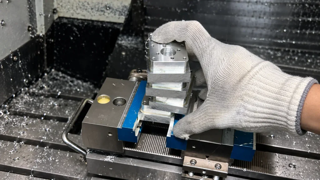
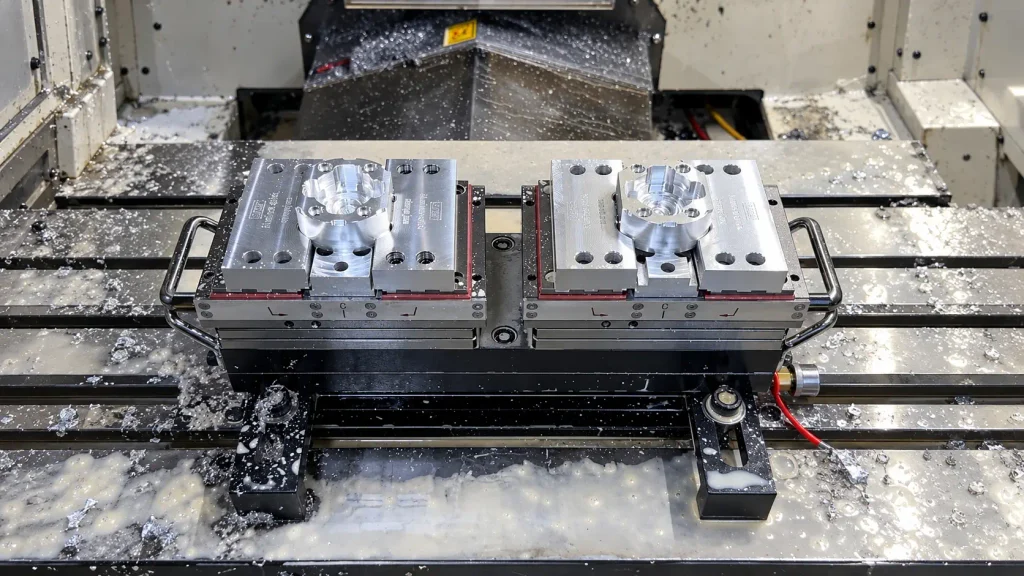
Soft jaws are machined to provide contact surfaces suited to a particular workpiece. They are especially useful for irregular profiles and second operations, where standard flat jaws may offer little support.
Their value lies in more than matching the outline. A recess can locate a housing on selected machined surfaces while supporting it for underside machining. Relief around corners and non-locating areas helps the part seat correctly. Chips trapped beneath those contact surfaces can change its position, so clean seating is essential.
Chucks and Collets
Chucks use movable jaws to grip a workpiece, while collets close around a matching diameter. Both hold round parts for turning and can secure components on rotary axes for milling. Chucks generally accommodate a wider range of sizes; collets operate within a narrower gripping range.
For shafts, grip length and unsupported overhang matter as much as the device itself. Excessive overhang can allow deflection or vibration. Thin-walled tubes present another concern: radial pressure can distort them, even when the grip appears secure.
Mandrel Fixtures
Mandrel fixtures hold parts through an internal bore, leaving the outside accessible. This makes them useful for sleeves, bushings, and rings when the outside diameter needs to remain concentric with a machined bore.
An expanding mandrel grips from inside, often with an axial stop to establish the part’s position along it. The bore becomes part of the locating arrangement, so its size, condition, and contact length matter. Excessive expansion can distort a thin sleeve.
Fixture Plates and Clamping Systems
Large plates and irregular components may not fit conveniently in a vise. A fixture plate provides a base for stops, locating pins, supports, and clamps arranged around the workpiece.
Strap clamps hold from above, while edge clamps can leave more of the top surface accessible. Neither arrangement works well if the clamping force bends the part against an unsupported gap. Support beneath the loaded area and clearance around the toolpath are therefore central to the layout.
Modular Fixtures
Modular fixtures combine reusable locating elements, supports, and clamps into different setups. They suit prototypes, changing jobs, and families of parts that do not justify a separate fixture for every geometry.
The components can be reused, but the completed arrangement still needs checking. Repositioning a support or clamp changes how forces pass through the setup and may affect tool clearance. For frequent repeat production, a dedicated arrangement can simplify loading and reduce repeated setup work.
Vacuum Fixtures
Vacuum fixtures use a pressure difference to hold a workpiece against a supporting surface. Thin panels and cover plates can benefit because the top face remains accessible without conventional jaws pressing on the edges.
Available grip depends on the vacuum level and effective sealed area. Cutting a through-feature can open the sealed region and reduce holding force. The fixture layout must account for the part’s condition throughout the cut, with suitable seals and, where necessary, stops to resist sideways movement.
Dedicated Fixtures
Dedicated fixtures are built around a particular part or operation. They can combine shaped supports, locating pins, and clamps to hold components that standard devices cannot accommodate conveniently.
For repeat production, their advantage is often the loading arrangement. Defined contact points help each workpiece seat in the intended position without repeated manual alignment. That benefit must justify the design and manufacturing effort, particularly when quantities are small or the part is likely to change.
Fixture Planning for Secondary Machining and Thin-Walled Parts
Workholding becomes more demanding after the first operation removes the original gripping stock. The next setup must locate the partly finished component, support its remaining structure, and leave the required surfaces accessible.
Maintaining Datum Relationships After Flipping
When an aluminum housing is flipped to finish its underside, the second setup needs to preserve the relationship between the new surface and features already machined. A shaped recess alone does not establish that relationship. The fixture needs selected reference faces or holes that locate the part consistently.
Contact areas must also allow the workpiece to seat fully. A corner radius, burr, or trapped chip can hold it away from the intended reference surface. Relief around non-locating areas helps avoid interference, while clean locating contacts make the setup more repeatable. Re-establishing the machining coordinates cannot compensate for a part that is seated incorrectly.
Controlling Deformation During Clamping
A thin-walled part can remain firmly held while bending under clamping pressure. If it is finish-machined in that condition, elastic recovery after release may change its dimensions.
The fixture therefore needs a suitable load path: clamps should act toward supported areas rather than push against unsupported walls. Broader contact surfaces can distribute pressure, but they do not replace support where the load acts. As roughing removes material and reduces stiffness, the finishing operation may require a different support arrangement or clamping force.
Inspection closes the loop. Unless the drawing specifies a constrained inspection condition, checking critical dimensions after release helps reveal distortion that measurements taken while clamped may conceal.
How We Develop CNC Fixtures for Custom Parts
At ZH Precision, we review the drawing and machining sequence to plan how each part will be located, supported, and clamped. When standard workholding is unsuitable, we machine shaped jaws or dedicated fixtures around the available reference surfaces and critical dimensions.
Our fixture layouts provide support beneath loaded areas, relief around non-locating features, and clearance for tools. Before production, we check part seating and inspect the first component after release, including the relationship between features machined in different setups. For repeat batches, we also consider loading access and chip removal.
Conclusion
CNC fixtures do more than keep a workpiece from moving. Their locating contacts, support positions, and gripping method shape how the part can be machined and how reliably its features remain related across operations.
Standard workholding suits many parts. Others need shaped jaws or dedicated tooling because of their geometry, thin sections, or secondary machining requirements. At ZH Precision, we review these needs as part of the machining plan. Send us your drawings and CAD files to discuss workholding and production requirements for your custom parts.



