


This guide starts with blank preparation, then examines bend allowances, bend radii, reliefs, hole placement, and stiffening features. It also covers finishing, assembly, and drawing requirements that can affect production. The aim is to explain how design choices influence manufacturing and help you prepare parts with achievable dimensions, workable features, and clearly defined requirements.
Blank Preparation
Blank preparation establishes the outline and openings, but their accuracy must be judged against the finished part. A clearance hole on a flat panel and a locating hole on a bent flange may need different production plans, even if they have the same diameter. Identify which features control fit, positioning, or assembly before deciding how to produce them.
Laser Cutting
Laser cutting gives designers flexibility to create irregular profiles and openings without dedicated cutting dies. It is useful when several part designs share a sheet or when geometry changes during development.
The main concern is often the material left between cuts. Narrow strips around ventilation slots or small tabs can distort or become fragile during handling. Increasing the spacing or changing the opening layout may make the blank easier to process without affecting its function.
For precision openings, confirm whether the cut accuracy and surface condition meet the required fit. Some features may need secondary machining. Supply nominal CAD dimensions and let the manufacturer apply kerf compensation during programming.
Punching
Repeated holes and slots can suit CNC punching, especially when their shapes match available tools. Standardizing these features reduces tool changes and can avoid custom tooling.
Punching also affects the surrounding sheet. Closely spaced openings may distort a panel, while overlapping hits used to create a contour can leave a scalloped edge. These effects matter where the part must sit flat, seal against another surface, or provide a consistent reference for bending. Specify the necessary deburring and edge condition at those locations.
Waterjet Cutting
Waterjet cutting avoids a heat-affected zone, making it useful when thermal effects are a concern. However, edge taper and striations may affect how the blank contacts another surface.
An exposed outer profile may accept these characteristics; an edge used against a bending backgauge or as a mating surface may need a better finish. Identify those edges so cutting quality or secondary processing can be selected according to their function.
ZH Precision provides custom sheet metal fabrication services, including laser cutting, CNC bending, welding, secondary machining, and surface finishing. We manufacture enclosures, brackets, panels, and chassis to your drawings, from prototypes to production quantities, with no minimum order quantity.
Forming
Bending changes the relationship between features that were cut into the same flat blank. Holes on opposing flanges, for example, must align after forming—not simply in the flat pattern. Sheet metal DFM therefore needs to account for material deformation, tooling access, and the sequence used to create the finished shape.
Bend Allowance and Finished Dimensions
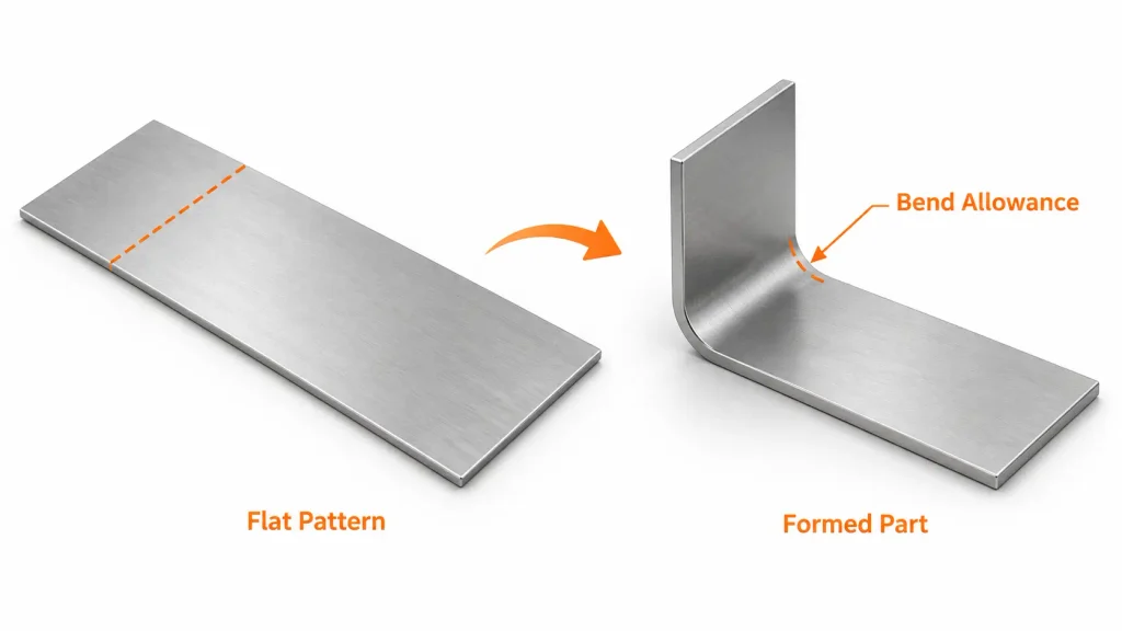
The length of a flat blank cannot be calculated by simply adding the finished flange dimensions. Material within each bend forms a curved section, whose developed length is accounted for by the bend allowance. Thickness, inside radius, bend angle, and the neutral-axis position influence this value.
CAD software can generate a flat pattern, but its bend settings must match the intended production conditions. Incorrect settings can shift mounting holes or leave an enclosure too wide or too narrow.
Define critical dimensions on the formed part and confirm who will prepare the production flat pattern. This gives the manufacturer a clear target while allowing the unfolding calculations to suit the actual material and tooling.
Bend Radius and Material Direction
A smaller bend radius creates more deformation at the outer surface, increasing the risk of cracking. The acceptable radius depends on the alloy, temper, thickness, and rolling direction. A radius that works in a ductile steel sheet may be unsuitable for hardened aluminum. If your drawing specifies a gauge number, use a sheet metal gauge calculator to confirm the nominal thickness for the specified material before reviewing bend radius requirements.
For a part with bends in perpendicular directions, one bend may be less favorably oriented relative to the rolling direction. Increasing the radius or selecting a more formable material condition may be necessary. Where function permits, use consistent radii that match available tooling to simplify production.
Flange Length and Tool Access
A flange must be long enough to remain supported by the die during bending. Shortening it to save space can make the feature difficult to form with standard tooling.
Access becomes especially important on channels, deep enclosures, and parts with return flanges. An earlier bend may block the punch from reaching the next one, or the formed part may become difficult to remove from the tool. Review the complete bending sequence before finalizing closely spaced bends and enclosed shapes.
Bend Relief and Nearby Openings
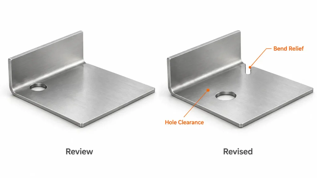
Where a bend ends beside material that remains flat, the junction can tear or pull the adjacent edge out of shape. A relief cut separates these regions and gives the flange room to move. It must extend beyond the deformation zone; a shallow slit may leave the same interference in place.
Holes and slots near a bend can also stretch or shift. Check their edges against the bend region, particularly when they receive fasteners or locate another component. If an opening cannot move, a suitable relief or machining after forming may provide a workable solution.
Reliefs also leave visible gaps. Their shape and position should suit any sealing, welding, or appearance requirements.
Stiffening Features
A large panel may need greater stiffness without the weight and cost of thicker sheet. Edge flanges, beads, and formed ribs can change its cross-section to resist flexing. Position them according to the expected load and keep them clear of mounting surfaces and adjoining components.
Hems can stiffen exposed edges and reduce contact with sharp cut surfaces, but they require additional forming and sufficient material ductility. Account for the folded thickness wherever the edge enters a slot or overlaps another part.
Finishing and Assembly Considerations
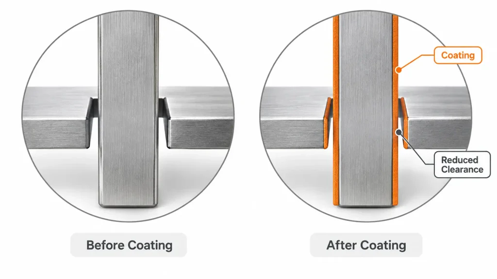
A sheet metal enclosure that fits before powder coating may become difficult to assemble afterward. Coating buildup reduces clearance in slots and holes and adds thickness to overlapping edges. Define whether critical dimensions apply before or after finishing, and identify any threads, grounding points, or mating surfaces that require masking.
Visible surfaces also need clear requirements. Hanging points and fixture contacts can leave marks or uncoated areas, so indicate where these are acceptable rather than leaving their location to production.
For assembly, tabs, slots, and locating flanges can position components before screws or rivets are installed. Applying design for assembly (DFA) principles can help simplify positioning and fastening. Allow enough clearance for cutting and bending variation, including the finish, while keeping the movement within the assembly’s requirements. Check that tools can reach the connection after all surrounding panels are in place.
Choose joining methods according to loading, access, and service needs. Rivets suit permanent connections, while self-clinching nuts can provide reusable threads when the sheet material and thickness suit the hardware. Welding can create rigid joints, but distortion may affect nearby mounting faces or hole alignment.
Design Review and Drawing Preparation
A 3D model defines the part’s shape, but it may not explain which dimensions matter most. Before releasing a sheet metal design, identify the interfaces that control mounting, alignment, and fit. These requirements help the manufacturer decide where to focus process control and inspection.
Specify the material grade, condition, thickness, and finish. If material selection is still open, our sheet metal materials guide can help you compare options before finalizing the drawing. Show critical dimensions on the formed part, with clear references for hole positions, flange heights, and mating surfaces. Avoid dimensioning every feature through a chain of bends when its position can be defined directly from a functional reference.
If you supply both a flat pattern and a formed model, keep their revisions consistent and confirm which file governs production. Include hardware specifications, weld locations, and masking requirements where applicable. This reduces the need for the manufacturer to infer details that could affect the finished part.
A final review should also check whether tight tolerances are necessary for function. A cover edge may allow more variation than a locating hole; distinguishing them can reduce manufacturing effort while preserving the fit that matters.
Final Thoughts
Sheet metal DFM starts with the finished part’s requirements and works back through the operations needed to achieve them. A mounting hole must remain correctly positioned after bending, a coated slot must still accept its mating tab, and a flange must be accessible to the forming tool. Checking these relationships before production helps avoid changes after parts have already been cut or formed.



