

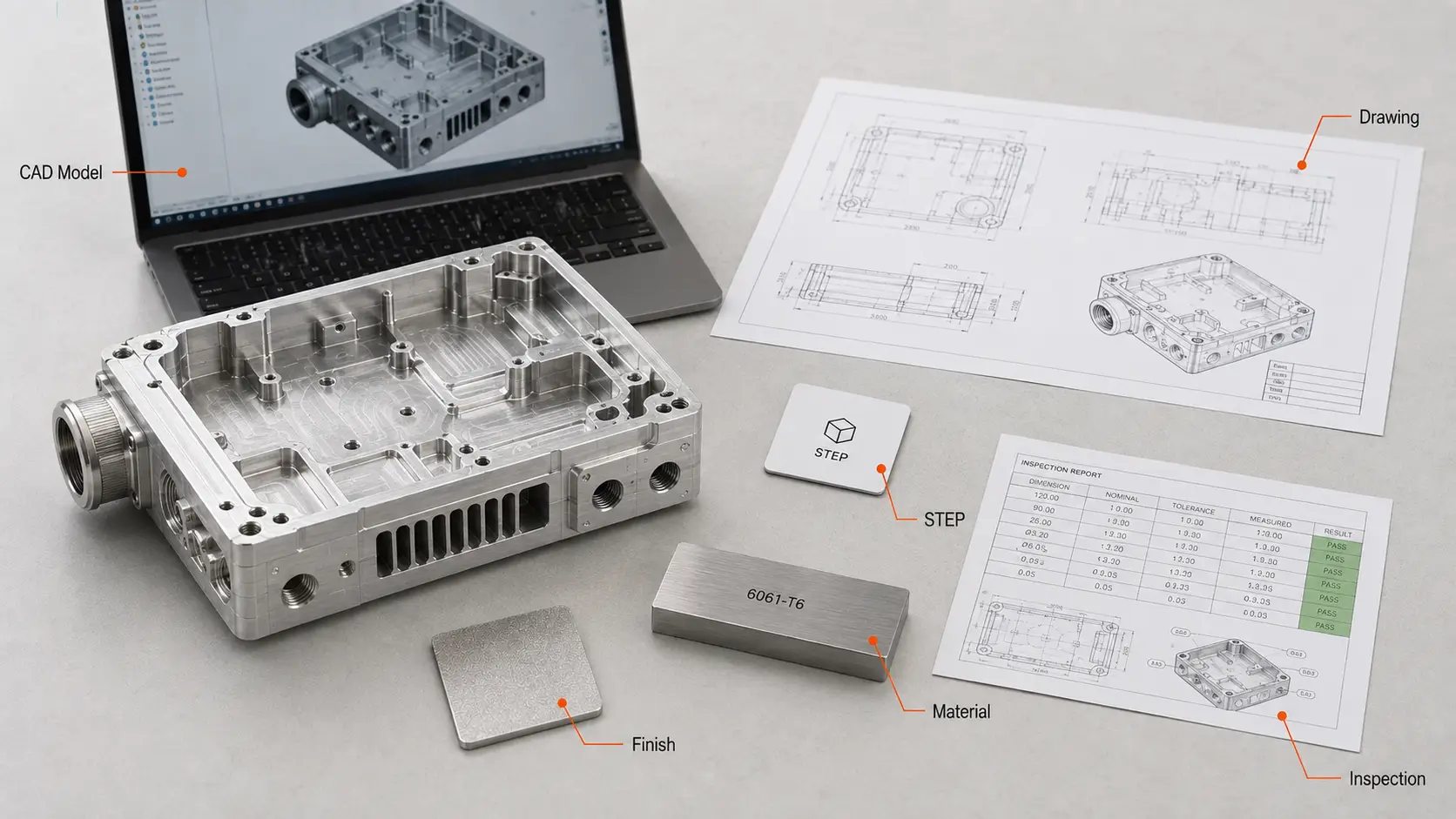
This gap is where many quoting delays start. The problem is often not a missing file, but missing context about the manufacturing requirements behind it.
A useful RFQ gives the supplier enough information to understand both the part and the requirements that affect machining, inspection, cost, and lead time.
If you are still deciding how CNC machining fits into the development process, What Is CNC Prototyping? explains how machined prototypes support fit, functional, dimensional, and manufacturing validation.
Why Prototype RFQs Get Quoted Wrong
A production RFQ often arrives with a more mature drawing, a stable tolerance scheme, and clearer inspection requirements. A prototype RFQ may still contain dimensions, tolerances, or features that are under review.
That uncertainty affects the quote.
If a drawing does not distinguish functional requirements from cosmetic ones, the supplier has to decide how seriously to treat every callout. The same problem occurs when tight tolerances come from a template rather than a confirmed engineering requirement.
A supplier may price the part around the tightest interpretation, increasing machining and inspection cost. The opposite can also happen if a feature appears non-critical but actually controls assembly or testing.
A CNC prototype manufacturer can quote more accurately when the RFQ clearly separates controlled requirements from dimensions that still have design flexibility.
Why Prototype Status Matters
Labeling a job as a prototype changes how the supplier may plan the work.
A one-off part may not justify the same fixture investment as a repeat production job. The supplier may use a vise, soft jaws, modular fixturing, or another flexible workholding method instead of dedicated production tooling.
Material sourcing can also change. For a small quantity, available stock may be more practical than sourcing material around a long-term production requirement.
Inspection planning depends on the prototype stage as well. A part used to check overall fit may only need several key dimensions verified. A prototype built around a press-fit bore may require much tighter control on that feature.
Prototype status does not mean relaxing every requirement. A bearing bore still needs the specified fit, and a sealing surface still needs the geometry and finish required for the test.
Stating the development stage helps the supplier choose an appropriate machining and inspection approach.
3D Model and 2D Drawing Requirements
The 3D model and 2D drawing serve different purposes in a CNC prototype RFQ. They become especially important together when the part contains controlled fits, GD&T, threads, surface requirements, or inspection criteria.
What a STEP File Defines
A standard STEP file supplied for quotation primarily communicates part geometry. It shows surfaces, holes, pockets, bosses, and other modeled features.
The supplier can use the geometry to estimate machining time, check tool access, identify possible setups, and determine whether the part requires milling, turning, or multi-axis machining.
Depending on how the file is exported, STEP can also contain PMI and other manufacturing information. In many prototype RFQs, however, the supplier still relies on a separate drawing for tolerances, datum references, thread specifications, material, heat treatment, surface requirements, and inspection notes.
A 3D model usually tells the supplier what the part looks like. It does not always communicate which features control function or assembly.
Two parts with identical CAD geometry can therefore require different machining and inspection strategies.
When GD&T Is Necessary
A prototype does not automatically need a complete GD&T scheme. It does need enough dimensional information to control the feature relationships that matter.
For an early form or packaging check, a simplified drawing with several critical dimensions and a general tolerance may be sufficient.
A functional prototype may need more control. Bearing locations, mounting patterns, sealing faces, shaft alignment, and other related features may require datum references or geometric tolerances.
GD&T becomes particularly useful when the relationship between features matters more than the size of one feature by itself.
Position, flatness, perpendicularity, profile, and similar controls should therefore follow the functional requirement rather than whether the part is labeled prototype or production.
Material Requirements
Material information should go beyond a broad category such as aluminum, steel, or plastic when material behavior affects the test.
Material for Functional Prototypes
If the prototype will be evaluated for mechanical performance, thermal behavior, corrosion resistance, weight, or loading, specify the intended material grade and relevant condition.
“Aluminum” is not a complete specification.
6061-T6 and 7075-T6 differ in strength, cost, machinability, and availability. Substituting one for the other can make a functional test less representative of the final component.
Where relevant, include:
- material grade
- temper or condition
- hardness
- heat treatment
- other material requirements that affect performance
Not every prototype needs all of this information. Include it when the material property affects the engineering result.
When Material Substitution Is Acceptable
A substitute material may be reasonable when the prototype only needs to confirm geometry, assembly space, or basic fit.
For example, a lower-cost or more readily available aluminum grade may work when strength and material behavior are not part of the test.
The RFQ should state whether substitution is allowed.
Material substitution may be unsuitable when weight, anodizing response, corrosion behavior, thermal performance, or surface treatment forms part of the evaluation.
Critical Tolerances
Tolerance requirements have a direct effect on CNC prototype pricing.
The supplier needs to know where dimensional control matters and where a standard machining tolerance is sufficient.
General Tolerances vs. Fit-Critical Dimensions
Applying tight tolerances to every dimension does not necessarily make a prototype more useful.
It usually increases machining and inspection cost. It can also make it harder to distinguish functional requirements from non-critical geometry.
A better approach is to apply a general tolerance to ordinary dimensions and identify tighter requirements only where needed.
For example, a housing may contain one bearing bore and several non-critical exterior surfaces. The bore may require close control while the surrounding geometry can use a general machining tolerance.
For a deeper explanation of how tolerance requirements affect machining strategy and cost, see CNC Machining Tolerances.
Common Fit-Critical Features
Critical dimensions often occur where components locate, contact, seal, or move against each other.
Common examples include:
- bearing bores
- shaft fits
- locating holes
- dowel pin holes
- mounting hole patterns
- mating faces
- sealing surfaces
- datum features
- threaded interfaces
- controlled clearances
A prototype intended to validate one of these interfaces should carry an actual engineering requirement rather than a placeholder tolerance.
The supplier does not need every dimension to be tight. The supplier needs to know which dimensions determine whether the interface works.
Prototype Quantity and Production Volume
Quantity affects more than the total number of parts on the quote. It can change workholding, programming, inspection, and setup strategy.
Prototype Quantity
State the number of prototype parts required.
A quantity of one may justify simple, flexible workholding. A quantity of ten may justify additional fixture preparation if it reduces repeated setup time.
This is why ten parts are not always priced as ten times the cost of one.
Programming, setup, and inspection effort can spread across the quantity.
Expected Production Volume
If the prototype may lead to repeat orders or production, include that information when it is known.
A project such as:
5 prototypes → 50 validation parts → 500 repeat parts
may influence fixture and process planning even if the current RFQ only covers the first five parts.
If future volume is unknown, state that it is still under review rather than guessing at a number.
Surface Finish and Secondary Operations
Surface requirements should match the function of the prototype.
Specify processes such as anodizing, bead blasting, passivation, plating, polishing, powder coating, or heat treatment when they affect appearance, corrosion resistance, fit, or performance.
If surface texture matters, specify the required roughness instead of using a general description such as “smooth finish.”
A requirement such as Ra 0.8 μm communicates much more clearly when surface condition affects a sealing face, sliding interface, or other functional area.
Cosmetic surfaces should also be identified when appearance matters.
Masking requirements are important when threads, electrical contact areas, sealing surfaces, or tightly controlled dimensions must remain free of coating.
Finishing can also change dimensions. Coating thickness should therefore be considered when it affects a fit or clearance.
Inspection Requirements
Prototype parts do not automatically need less inspection than production parts.
The correct scope depends on the dimensions being validated and the risk associated with getting them wrong.
A cosmetic prototype may only need a basic dimensional check. A prototype used to validate a bearing fit or sealing interface may require detailed measurement of those features.
The RFQ should also distinguish between inspection and inspection documentation.
A supplier may inspect critical dimensions during machining and final inspection without automatically providing a formal report.
If documentation is required, specify the expected format. Examples include:
- dimensional inspection report
- CMM report
- First Article Inspection report
- material certificate
- certificate of conformance
- other project-specific records
Also identify which dimensions the report needs to cover.
A complete dimensional report on every feature may add unnecessary cost when only a few dimensions control the prototype.
Lead Time, Revision Control, and DFM Feedback
State the required delivery date when timing matters. Include the shipping destination if it affects the schedule.
If the deadline is flexible, say so. Schedule flexibility may give the supplier more options for material sourcing, machine scheduling, inspection, and secondary processing.
Revision control is equally important because prototype designs can change quickly.
The RFQ should identify the current:
- part number
- CAD revision
- drawing revision
Make sure the CAD model and drawing refer to the same revision.
A supplier can quote Rev A correctly and still machine the wrong geometry if Rev B appears later without clear revision control.
Inviting DFM feedback is also useful while the design remains open to change.
The machining team may identify a difficult feature, suggest a more practical tolerance, recommend a larger internal radius, or discuss an alternative material before machining begins.
Thin or tall walls are a common example. Machining stability depends on height, support, geometry, material, tool access, and tolerance. CNC Machining Wall Thickness explains these relationships in more detail.
DFM feedback does not guarantee a lower quote. It reduces the chance that a manufacturing problem appears after the job has already started.
CNC Prototype RFQ Checklist
Before sending a CNC prototype RFQ, confirm that the supplier has enough information to understand both the geometry and the manufacturing requirements.
| RFQ Item | What to Provide |
|---|---|
| 3D CAD model | STEP, Parasolid, or another agreed CAD format |
| 2D drawing | Critical dimensions, tolerances, GD&T, threads, and manufacturing notes |
| Prototype purpose | Fit, assembly, function, appearance, load testing, or another validation goal |
| Material | Grade and relevant temper, condition, or hardness |
| Quantity | Current prototype quantity and expected repeat volume if known |
| Critical features | Fits, mating interfaces, datums, sealing surfaces, and other controlled features |
| Surface requirements | Finish, roughness, color, cosmetic areas, and masking if required |
| Inspection | Critical dimensions and any required inspection documentation |
| Lead time | Required delivery date and shipping destination |
| Revision | Current CAD and drawing revision |
| Design flexibility | Features, tolerances, materials, or finishes that can still change |
Not every RFQ needs every item in the table.
A simple geometry prototype may only need a CAD model, material, quantity, and target delivery date. A functional validation part may require a controlled drawing, material condition, inspection requirements, and clearly identified critical interfaces.
If some tolerances, materials, or features remain flexible, identify them during the RFQ. This gives the machining team room to recommend a practical manufacturing approach before the design becomes fixed.
ZH Precision provides CNC prototyping services for custom parts based on 2D drawings and 3D CAD files. CNC milling, turning, 3-axis, 4-axis, and 5-axis machining support different prototype geometries and manufacturing requirements.
When requesting a quotation, provide the available CAD data, material, quantity, finish, target lead time, and any critical tolerance or inspection requirements. Requirements that remain open can be identified during quotation instead of being treated as fixed assumptions.
Conclusion
A useful CNC prototype RFQ does more than describe the shape of a part. It communicates the requirements that influence how the supplier machines, inspects, and quotes it.
CAD geometry, material, quantity, tolerances, finishing, inspection, lead time, and revision information all help reduce uncertainty during process planning.
Not every prototype needs a completely frozen production drawing. Early-stage projects can still contain open decisions, but those decisions should be identified clearly.
The better the RFQ separates critical requirements from flexible ones, the easier it becomes for the supplier to quote the appropriate machining and inspection process.




