

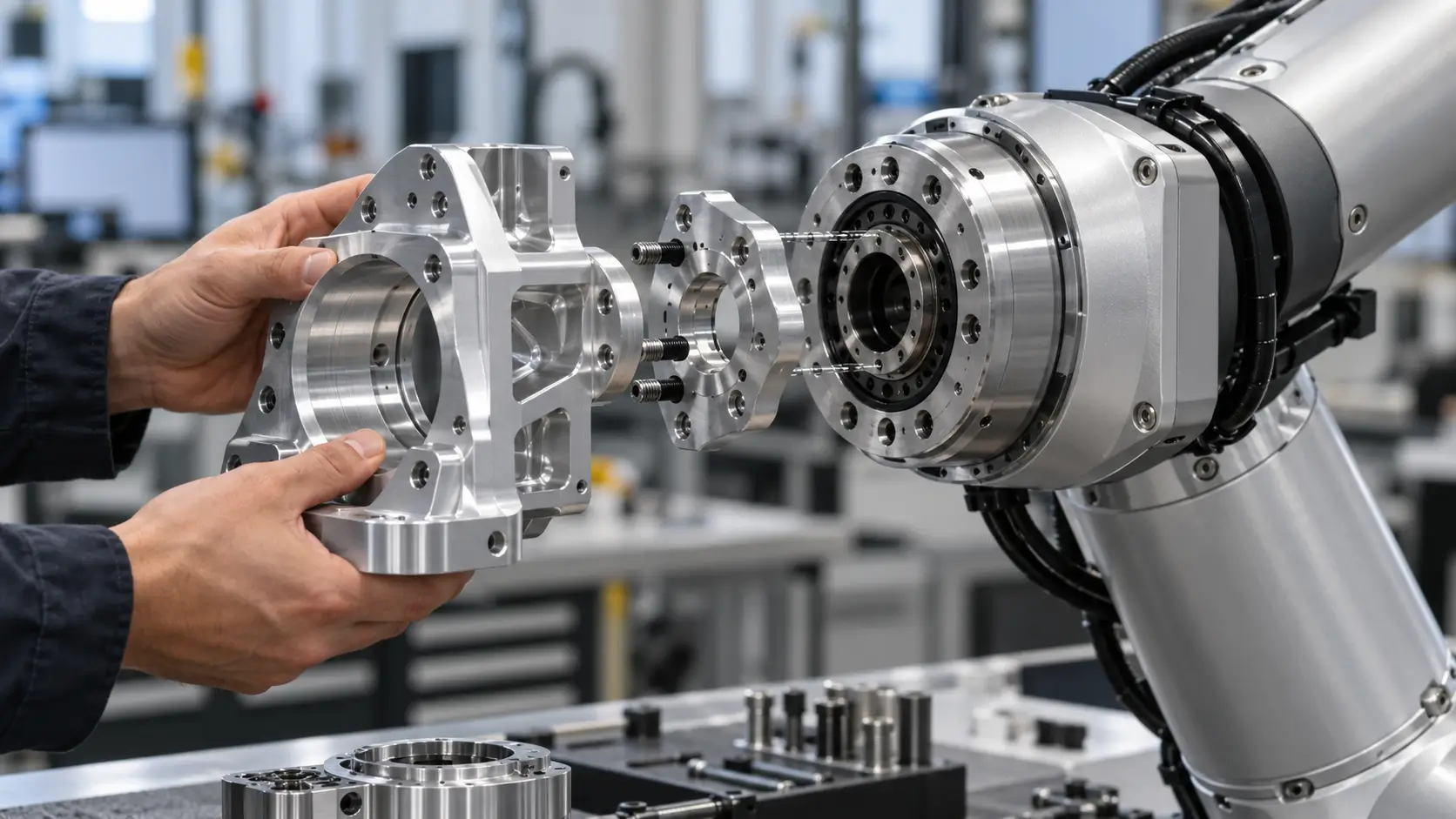
This distinction becomes important because many development delays occur after a prototype has already worked. A functional part may still contain features that are expensive to machine repeatedly, tolerances that were never reconsidered after the first build, or geometry that will need to change if the production process moves from CNC machining to die casting, sheet metal fabrication, or extrusion.
For teams using CNC prototyping services during product development, the objective should therefore be more specific than producing a physical sample. Each prototype should answer a defined engineering question and reduce uncertainty before the next design or manufacturing decision.
This guide explains where CNC prototyping fits in product development, what a CNC prototype can and cannot validate, how prototype results should drive design iteration, and what needs to be resolved before moving from prototype to production.
Where CNC Prototyping Fits in the Product Development Process
Product development generally moves through concept development, CAD design, physical validation, design iteration, design release, and production. CNC prototyping sits between digital design and production because some design assumptions cannot be verified reliably until the part exists in its intended material and can be assembled, measured, loaded, or machined.
CAD can confirm nominal geometry and simulation can predict many aspects of performance, but neither completely reproduces the interaction between manufacturing tolerances, material condition, workholding, tool access, assembly variation, and real loading. A digital assembly may show sufficient clearance while the physical parts interfere once tolerances accumulate. A wall may appear sufficiently rigid in the model but deflect during testing or machining. A deep pocket may look straightforward until the required tool length introduces deflection and makes the specified tolerance difficult to maintain.
CNC machining is particularly useful when the prototype needs to behave like an engineering component rather than simply reproduce its appearance. When the final part will also be CNC machined, the prototype can often use the same alloy, temper, and material condition while holding dimensions close to production requirements. This provides a useful basis for evaluating fit, load response, wear, assembly, and machining feasibility.
When production is expected to move to another manufacturing process, the CNC prototype still provides valuable geometric and functional information, but the limits of that validation need to be understood. A machined aluminum prototype cannot reproduce die casting solidification, porosity, draft requirements, or as-cast material structure. It also cannot validate sheet metal forming behavior or the cross-section constraints of extrusion.
A practical development sequence is:
Concept → CAD & DFM → CNC Prototype → Test & Iterate → Design Freeze → Production-Intent Build → Production
The CNC prototype is an important validation stage within that sequence, not the final proof of production readiness.
What a CNC Prototype Can Validate
A CNC prototype provides the most value when the engineering team defines what the build is intended to prove before machining begins. For most product development projects, the strongest areas of validation are assembly interfaces, functional behavior, material response, and manufacturability.
Form, Fit, and Assembly Interfaces
A physical prototype confirms whether the part occupies the correct space within the assembly and whether mating features engage as intended. This is particularly useful for locating holes, bearing interfaces, sealing surfaces, dowel locations, fastener patterns, alignment features, and other geometry whose function depends on how several components interact.
Tolerance stack-up often becomes more obvious during physical assembly than during drawing review. Two dimensions can each meet their individual tolerance requirements and still create interference when their worst-case conditions occur together. Several clearances can also accumulate and create more movement or misalignment than the assembly can accept. In these situations, the problem is not necessarily that an individual feature is out of tolerance. The tolerance scheme itself may not reflect how the assembly functions.
Prototype testing provides a chance to identify which dimensions actually control fit and which have sufficient design margin. That information should eventually be reflected in the production drawing. Critical mating and locating features may require tighter control, while unrelated geometry should not automatically inherit the same tolerance level.
Functional and Material Behavior
A CNC prototype can also be used to evaluate how the component behaves under realistic operating conditions. When the production part will remain CNC machined, using the same alloy, temper, and material condition makes the prototype significantly more representative of final-part behavior.
Depending on the component, engineers may evaluate deflection under load, fastening performance, wear at contact surfaces, thermal response, repeated cycling, or stability within an assembly. These tests are most meaningful when the material condition matches the property being evaluated. A substitute material may still be suitable for checking geometry or assembly, but it cannot confirm strength, wear resistance, thermal behavior, or other material-dependent requirements in the same way.
The production process also affects how far this validation can be carried. A CNC-machined prototype can confirm many functional assumptions for a future cast or formed component, but the final process may introduce different mechanical properties, residual stresses, porosity, grain structure, or forming effects. Those properties should be validated again once the production material and manufacturing route have been finalized.
Manufacturability and Machining Accessibility
Machining the prototype provides a direct DFM check because geometry that appears reasonable in CAD can behave differently once tool access, cutter rigidity, workholding, and cutting forces are involved.
A deep pocket may require a long-reach cutter that introduces tool deflection. A thin wall can move under cutting force and make the intended tolerance difficult to maintain. A very small internal radius may require a smaller tool, increasing cycle time and reducing tool rigidity without providing a meaningful functional benefit. Features located behind surrounding geometry may also be reachable by the cutter itself while remaining difficult for the tool holder, fixture, or spindle to access safely.
These problems do not necessarily mean the part cannot be machined. A skilled machinist may still produce an acceptable prototype using additional setups, specialized tooling, slower cutting conditions, or manual intervention. The more important question is whether the same approach remains stable and economical when the design moves into repeat production.
This is one of the most useful lessons a CNC prototype can provide. A feature can be technically machinable and still be a poor production design.
What a CNC Prototype Cannot Validate on Its Own
A successful prototype confirms specific design assumptions, but several important production questions remain outside the scope of a single prototype build.
Production Repeatability
Producing one or several acceptable prototypes does not demonstrate that the same results can be maintained across repeat production.
Longer runs introduce variables that may not appear during an early build. Workholding needs to locate the part consistently from cycle to cycle, cutting tools gradually wear, material lots can vary, and repeated setups introduce another source of dimensional variation. A feature that was carefully adjusted during prototype machining may therefore become much more difficult to control once production volume increases.
Prototype machining can also tolerate additional manual effort. A machinist may spend extra time adjusting a setup, inspect every critical dimension, or use conservative cutting parameters because the immediate priority is obtaining a valid part. Those decisions can be reasonable during development but inefficient as the basis of a repeatable manufacturing process.
Production readiness therefore requires confirmation that the machining and inspection strategy can reproduce the required result consistently, not simply that one acceptable part has already been made.
Final Production Process Behavior
A CNC prototype cannot fully validate a final component that will be manufactured using a different process.
A machined aluminum part may confirm overall geometry, assembly fit, and many functional requirements, but it does not reproduce the conditions of die casting. Draft, parting lines, ejector locations, wall thickness, solidification behavior, porosity risk, and machining allowances become relevant only when the part is designed around the casting process.
The same limitation applies to sheet metal fabrication. A machined prototype cannot confirm bend behavior, springback, bend sequence, minimum flange length, or access for forming tools. An extrusion introduces a different constraint because the primary geometry must be producible as a continuous cross-section.
This is why changing the production process after prototype approval often requires another DFM review. The prototype may still have validated the product concept, but it has not automatically validated how the final manufacturing process will create the part.
Production Cost and Scalability
Machining feasibility and production economics are not the same thing.
A prototype may be straightforward to make when cost is secondary to speed and design validation. That same geometry can become expensive at higher quantities if it requires large amounts of stock removal, several setups, long-reach tooling, five-axis positioning, unusually small cutters, or extended inspection time.
Tolerances can have the same effect. Holding a tight tolerance on one functional bore may be justified. Applying the same level of control to several non-critical features can increase machining and inspection cost without improving performance.
Production planning therefore needs to look beyond whether the prototype could be manufactured. It needs to determine whether the manufacturing route remains stable, efficient, and economically reasonable at the expected volume.
Turning Prototype Results Into Design Iteration
A prototype that reveals a problem has performed an important part of its job. The value of that result depends on whether the team can trace the problem back to a specific design, tolerance, material, or manufacturing condition.
A fit problem may originate from a particular tolerance stack rather than the entire assembly. A fracture may be linked to a local stress concentration around one radius. A machining problem may result from a pocket depth that forces excessive tool reach, while dimensional instability may be caused by a wall that is too thin for the required workholding and cutting conditions. Identifying the actual mechanism allows the next design revision to address the feature responsible instead of changing several unrelated areas at once.
The same logic should be used when deciding what to re-test. A change to a locating interface may require another assembly check. A revised structural rib may require another load test because the load path has changed. A tolerance revision may require another dimensional and fit review. Other previously validated requirements may remain closed if the team can show that the design change does not affect them.
This change-impact approach is more useful than either re-testing the entire design after every revision or assuming that a small CAD change cannot influence another requirement. Each prototype iteration should have a defined reason, and the next build should answer the engineering questions created by that change.
What to Resolve Before Moving From Prototype to Production
Moving from prototype to production should happen because the main development risks have been resolved, not because a certain number of prototypes has been completed. Before the design is released, the team should confirm that the geometry has stabilized, the drawing reflects the functional requirements learned during testing, major DFM issues have been addressed, and the intended production process is understood.
Design and Tolerance Confirmation
By the end of prototyping, the design should no longer change significantly between builds unless new test results justify the revision. Continuing to introduce small unrelated changes makes it difficult to determine what has actually been validated and can also create unnecessary risk when the project moves into production planning.
Drawing tolerances deserve the same review. Early prototype drawings often contain temporary or conservative values because the development team does not yet know which dimensions are truly critical. Once fit and functional testing have been completed, those values should be reconsidered.
A bearing bore, locating feature, sealing surface, or controlled mating interface may justify close dimensional control because its variation directly affects function. An exterior edge, clearance pocket, or unrelated feature may have much more tolerance available. Carrying prototype-level tight tolerances onto non-critical geometry adds machining and inspection work without improving the part.
Prototype inspection data should therefore be used to improve the production drawing, not simply confirm that the prototype passed.
Manufacturing and DFM Readiness
Manufacturing problems identified during prototyping should be resolved before they become permanent production workarounds. A feature that repeatedly requires a long, unstable tool should be reviewed. A thin wall that distorts during every setup should trigger a discussion about whether the geometry or tolerance can change. A very small internal radius that requires a dedicated cutter should be justified by function rather than remaining on the drawing by default.
This is also where feedback from the CNC prototype manufacturer can provide value beyond the finished part. The machining team has already seen how the geometry behaves during setup, cutting, inspection, and sometimes assembly. That experience can identify design features that are possible to manufacture but likely to cause higher cycle time, process sensitivity, or repeatability problems later.
If the final manufacturing method will change, a new DFM review is required around that process. A successful CNC prototype does not remove the need for casting DFM, sheet metal DFM, or extrusion-specific design review.
Inspection and Documentation Requirements
Prototype inspection should be determined by what the build is intended to validate. A visual or ergonomic prototype may need little dimensional reporting, while a prototype used to confirm a bearing fit, hole position, or critical assembly interface may require CMM inspection or a detailed dimensional report even if only one component is produced.
Production requires a more systematic approach because the question changes from whether one part meets the requirement to how that requirement will remain controlled throughout repeat manufacturing. Critical characteristics, acceptance criteria, inspection methods, inspection frequency, and documentation requirements should therefore be established before production begins.
Depending on the application, this may include first article inspection, dimensional reports, CMM data, material certificates, surface-finish verification, or customer-specific inspection records. The level of inspection should follow the actual risk of the feature rather than applying the same verification effort to every dimension.
A production-intent build can then verify the manufacturing route itself. At this stage, the objective is not simply to make another prototype. It is to confirm the planned workholding, machining sequence, inspection method, and repeatability assumptions before quantities increase.
Choosing a Production Process After CNC Prototyping
A validated CNC prototype does not automatically mean CNC machining is the best production method. The production decision depends on geometry, material requirements, tolerances, surface requirements, expected volume, product life, tooling investment, lead time, and the cost structure of each process.
Continue With CNC Machining
CNC machining remains practical when production volume is relatively low, the design may continue to change, the geometry naturally suits subtractive machining, or critical dimensions will require machining regardless of the upstream process.
One of its main advantages during the transition from prototype to production is that dedicated tooling is usually not required. Design changes can therefore be introduced without replacing a casting die or production forming tool.
The knowledge gained during prototyping also transfers directly into production planning. Workholding concepts, tool access, critical features, cutting strategy, and inspection methods have already been tested on real parts.
CNC machining becomes less attractive when cycle time, stock removal, setup count, or unnecessary complexity drives unit cost beyond what the expected volume can support.
Move to Die Casting
Die casting becomes more attractive when the project has sufficient repeat volume to justify dedicated tooling and the geometry can be adapted to casting requirements.
The production design normally needs to consider more consistent wall thickness, appropriate draft, a workable parting strategy, ejector locations, gate and overflow requirements, solidification behavior, and machining allowances for critical post-cast features.
This often means the CNC prototype should be treated as functional validation rather than a direct model of the final cast geometry. Features that were easy to machine from solid stock may need to change before tooling begins.
Moving to die casting therefore requires a process-specific DFM review even when the CNC prototype has already passed its functional testing.
Consider Sheet Metal or Extrusion
Sheet metal fabrication can be a better production route when the part can be redesigned around cut and formed sheet. Laser cutting and press brake bending can be economical even at relatively low quantities, while higher-volume stamping may justify dedicated tooling later.
The design needs to account for material thickness, bend radii, bend relief, flange dimensions, tool access, and forming sequence. These constraints are different from the machining limitations encountered during the CNC prototype.
Extrusion becomes relevant when the main geometry can be represented as a continuous cross-section. The extruded profile can then be cut to length and finished with CNC machining, drilling, threading, or other secondary operations.
The production process should be considered before the design is completely frozen. If the likely process is known during prototyping, its constraints can be incorporated into the next design revision instead of forcing a larger redesign later.
How to Choose a CNC Prototyping Supplier
A CNC prototyping supplier should do more than reproduce the CAD geometry. The supplier should understand what the prototype is intended to validate and select a machining and inspection approach that supports that purpose.
Machining and DFM Capability
Machining capability should match the actual part rather than simply providing a long equipment list.
Complex multi-face geometry may benefit from four-axis or five-axis machining because reducing setups can improve feature relationships and alignment. Rotational components may be better suited to CNC turning or mill-turn machining. The appropriate process depends on geometry, material, tolerance, size, and quantity.
DFM support is equally important. A capable supplier should identify thin walls, deep cavities, excessive tool reach, difficult workholding, unnecessarily small internal radii, tolerance risks, and features that add avoidable setups before machining begins.
For custom CNC prototyping, identifying one of these problems before the first build can be more valuable than simply producing the CAD exactly as supplied. A prototype iteration should ideally be used to validate the product, not to discover a manufacturing problem that was already visible during drawing review.
Inspection and Validation Support
The inspection method should match the purpose of the prototype.
A component built primarily to confirm appearance may need only limited dimensional verification. A part used for tolerance validation, bearing fit, sealing, or assembly alignment may require CMM inspection, a dimensional report, material certification, or first article data for selected features.
The supplier should therefore understand which characteristics actually matter to the test. Measuring every available dimension does not necessarily provide more useful validation if the critical interfaces have not been clearly identified.
Inspection results are most valuable when they can be connected back to the design decision the prototype is supposed to support.
Prototype-to-Production Support
The manufacturing relationship becomes more valuable when knowledge from prototype machining can carry into the next stage.
Once a supplier has already worked with the part, the team may understand where the difficult setups are, which walls are sensitive to cutting forces, which tolerances dominate inspection time, and which design changes were made during development. Losing that information during a supplier handoff can cause production engineering to rediscover problems that were already solved during prototyping.
ZH Precision supports CNC prototype development from DFM review through machining, inspection, surface finishing, and subsequent production. When a project continues into low-volume or repeat manufacturing, prototype feedback can be carried into the production review so that machining risks, drawing changes, and inspection requirements remain connected.
If you are developing a functional CNC prototype or preparing an existing design for production, provide the 3D CAD model, 2D drawing where applicable, material, quantity, and critical requirements for engineering review and quotation.
Conclusion
A CNC prototype does not prove that a design is ready for production. It proves specific assumptions about the design and provides physical evidence that can be used to improve the next engineering decision.
Form, fit, assembly interfaces, functional behavior, material response, and machining feasibility can all be evaluated during prototyping when the prototype is built around clearly defined validation objectives. Just as importantly, the machining process can expose geometry that is possible to manufacture but inefficient, unstable, or unnecessarily expensive to repeat.
Production readiness requires another level of review. The design needs to stabilize, tolerances need to reflect actual function, manufacturing problems need to be resolved, the final production process needs to be selected, and inspection requirements need to define how critical characteristics will remain controlled.
If production remains on CNC machining, much of the knowledge developed during prototyping can transfer directly into process planning and repeat production. If the component moves to die casting, sheet metal fabrication, extrusion, or another process, the design needs another DFM review based on the constraints of that manufacturing method.
The most useful CNC prototype is therefore not simply the version that works. It is the version that shows what has been validated, what still needs to change, and what must be confirmed before production begins.
FAQ
There is no fixed number of prototype iterations required before production. A simple component may reach a stable design after one or two builds, while a complex assembly may require several cycles of fit, load, thermal, or functional testing. The better measure is whether the remaining design risks are understood and whether each new prototype is still producing meaningful design changes.
A production-intent build becomes appropriate when the main geometry is stable, critical tolerances reflect actual functional requirements, major DFM issues have been resolved, the intended production process has been selected, and inspection requirements are defined. The purpose of this build is to confirm the manufacturing and inspection route rather than reopen basic design questions.
A 3D CAD model normally defines the nominal geometry, while a 2D drawing should identify critical tolerances, GD&T, fits, threads, surface requirements, or inspection requirements that cannot be communicated reliably through CAD alone. Material, quantity, finish, and the specific features or functions the prototype is intended to validate should also be provided so the machining and inspection plan can be matched to the project.




