

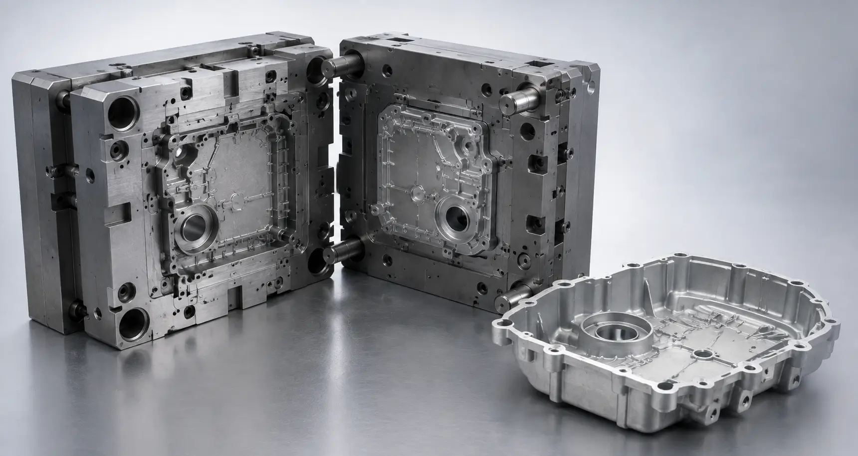
This guide walks through that full sequence: how die casting tooling gets built, what happens during a production run, and the trimming, secondary machining, surface finishing, and inspection steps that turn a raw casting into a finished part.
Die Casting Tooling Design and Construction
Every die casting run starts with the die itself, and the die is usually the largest single tooling investment and the longest lead-time item in the project.
The decisions made here affect much more than the shape of the casting. Parting lines, draft, metal flow, cooling, ejection, machining allowances, and dimensional requirements all need to be considered before the tool reaches production.
Die Casting Mold Components
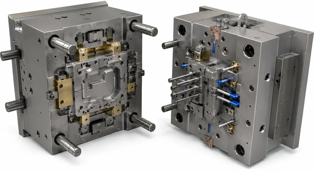
A production die casting mold is built from several functional components working together, not a single block of steel. The cavity and core define the part geometry, split across a fixed half mounted to the stationary side of the machine and a moving half that carries the ejector system.
Slides and movable cores handle undercuts or side features that cannot be formed by the straight-pull motion of the two main die halves. Cooling channels remove heat from the tooling and help maintain thermal balance, while ejector pins, sleeves, or other ejector elements push the solidified casting out of the die.
Runner and gate geometry also determine how molten metal enters the cavity. Vents and overflows provide paths for displaced air and the leading metal front, so they have to be considered together with cavity geometry rather than added after the tool has already been built.
Tool Steel Selection and Die Machining
Because die casting tooling is exposed to repeated thermal cycling, high cavity pressure, and contact with molten metal, working inserts and cavity components are commonly produced from hot-work tool steels such as H13 or another grade selected for the application.
Die construction typically begins with rough machining to remove most of the material before heat treatment. After the steel reaches its required working condition, critical cavity surfaces can be brought to final geometry using hard machining, grinding, EDM, or a combination of finishing processes depending on the tool design.
Heat treatment can introduce dimensional change, so final toolmaking operations need to account for the hardened condition rather than assuming that rough-machined geometry will remain unchanged. At ZH Precision, critical cavity dimensions are therefore evaluated through the complete tooling process rather than treated as finished at the rough-machining stage.
Draft and shrinkage allowance are also built into the die design. The required values depend on alloy, feature depth, geometry, surface condition, ejection direction, and other tooling conditions.
These allowances are established before the tool geometry is finalized because they affect both part release and the dimensional behavior of the finished casting. A die designed around one alloy and one part condition should not simply be assumed suitable for another material without reviewing those requirements.
Die Casting Tooling Lead Time
Tooling lead time depends on part complexity, cavity count, die size, and the number of slides, movable cores, or other actions required by the geometry, so there is no single lead time that applies to every project.
What is consistent is that tooling is usually the longest single stage in getting a new die cast component into production. Once cavity steel has been cut, a geometry change may require significantly more work than the same change made during the DFM and tooling-design stage.
Confirming the alloy, critical dimensions, machining allowances, surface requirements, and major geometry before committing to steel helps prevent tooling lead time from stacking with avoidable rework later.
Die Casting Tool Trials and Production Approval
Completing the tool does not immediately mean it is ready for repeat production. Initial trial shots are used to confirm how the cavity fills, whether the casting ejects correctly, how the part behaves during trimming, and whether the resulting geometry is consistent with the intended process.
The first samples can then be trimmed, machined where required, and inspected against the drawing. Filling conditions, flash, dimensional variation, ejection marks, visible defects, and other process results can be reviewed before the tooling is released.
If the samples identify a problem, the response may involve adjusting process parameters, changing local tooling conditions, modifying venting or overflow features, or correcting the tool itself.
This trial stage is the practical transition between building a die and establishing a repeatable production process. Resolving problems here is generally much easier than making the same corrections after regular production has started.
Die Casting Production Steps, From Melt to Ejection
Once the die and process are qualified, each production cycle follows the same basic sequence.
- Melting and holding. Metal is melted and maintained within the required process temperature range before entering the injection system.
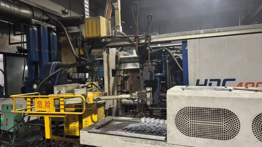
- Die closing and injection. The die halves close and clamp before molten metal is driven into the cavity at high speed and pressure. The cavity must fill before premature solidification prevents the metal from reaching thin sections or remote features.
- Intensification and solidification. After cavity filling, pressure is maintained or intensified while the metal is still responsive to the shot system. This helps maintain pressure on the casting during the early stage of solidification, although the ability to influence shrinkage decreases as the gate and surrounding metal solidify.
- Ejection. Once the casting has solidified enough to retain its shape, the die opens and the ejector system removes the casting so the next cycle can begin.
The exact process differs between hot-chamber and cold-chamber die casting, but high-pressure cavity filling and rapid solidification inside reusable steel tooling remain central to the process.
Trimming and Deburring After Die Casting
A part straight out of the die is not yet finished geometry. It is still connected to process features such as the biscuit, runners, gates, and overflow wells, along with possible flash at the parting line or around movable die components.
Trimming removes these larger process features. For repeat production, this is often performed using a dedicated trim die or press matched to the casting profile, allowing the excess material to be separated consistently rather than removed manually from every part.
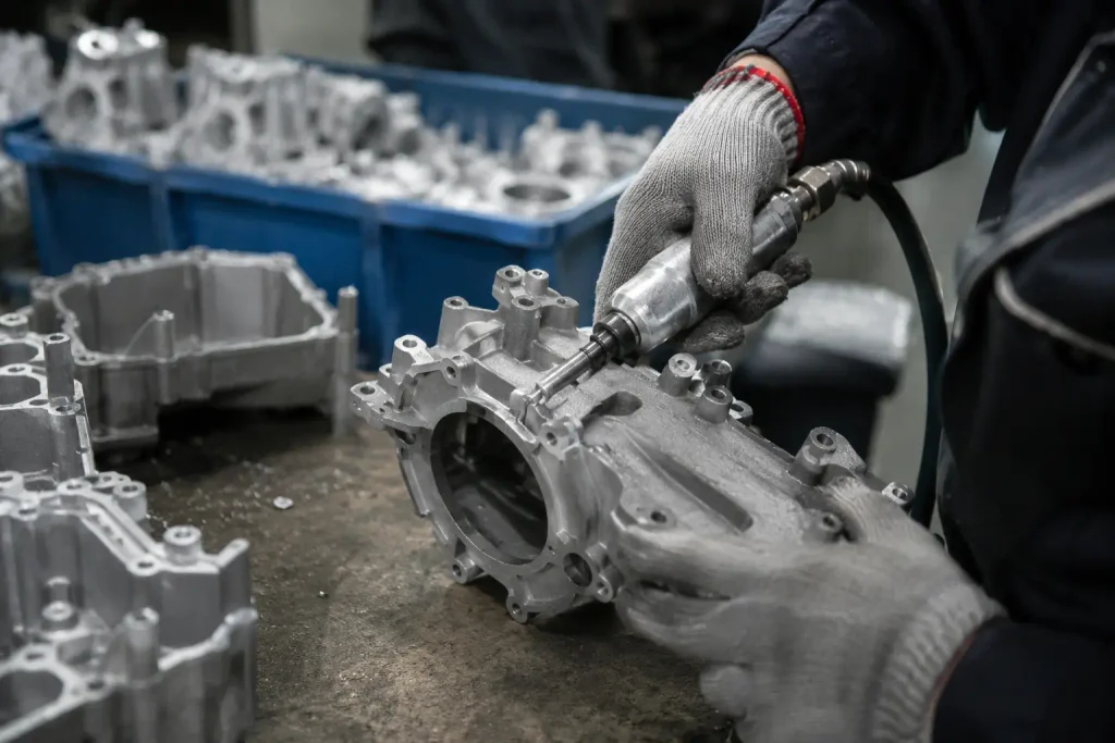
Deburring follows to clean up smaller remnants around gates, parting lines, ejector locations, and other areas that trimming does not finish completely. Depending on the geometry and surface requirement, this may involve tumbling, bead blasting, mechanical finishing, or localized manual deburring.
Suitable runners, biscuits, and other clean process returns can often be segregated for controlled remelting or recycling, depending on the alloy and foundry process.
Secondary Operations and Surface Finishing
Not every feature on a die cast part comes off the trim press ready for assembly. The amount of secondary processing depends on what each feature needs to do in the finished component.
A cosmetic exterior surface, a sealing face, a threaded boss, and a precision bearing bore may all require different post-casting operations even though they belong to the same casting.
CNC Machining of Critical Features
Die casting can produce near-net geometry with good repeatability, but some functional features still require CNC machining to reach their final specification.
Threaded holes, sealing surfaces, precision bores, locating features, and closely controlled mating interfaces are common examples. These features are typically cast with enough material for the required secondary operation and then machined relative to an appropriate datum or locating strategy.
This makes it possible to use casting for the majority of the geometry while reserving machining for the features that genuinely need tighter dimensional control.
The important question is therefore not whether the whole casting needs machining. It is which features cannot reliably meet their functional requirement in the as-cast condition.
For a part that could potentially be produced from billet or as a casting, the manufacturing decision depends on production volume, geometry, tooling investment, tolerance requirements, material utilization, and how much secondary machining remains after casting.
Surface Treatments for Die Cast Parts
Surface finish selection depends on the alloy, service environment, appearance requirement, corrosion exposure, wear conditions, and whether the coating affects a controlled dimension.
Aluminum die castings can receive conversion coatings, painting, powder coating, plating, and, for suitable alloys and applications, anodizing. Anodizing performance depends strongly on alloy chemistry. High-silicon casting alloys do not generally produce the same anodized appearance as wrought aluminum alloys, so the required finish should be reviewed together with the casting alloy rather than specified independently.
Zinc die castings are commonly plated, painted, powder coated, or treated with conversion coatings when additional corrosion protection or a particular appearance is required.
Magnesium castings can also require conversion coatings, e-coat, painting, powder coating, or other protective systems where the operating environment calls for additional corrosion protection.
The finish should ultimately be selected around what it needs to accomplish on the specific component. It should not be applied as a default operation simply because the part was produced by die casting.
Inspection and Quality Control in Die Casting
Inspection usually begins with a visual review of the casting for conditions such as excessive flash, cold shuts, incomplete filling, cracks, surface damage, or exposed surface porosity.
Dimensional inspection then focuses on the requirements defined by the drawing. Critical mating features, machined interfaces, datum-related dimensions, or closely controlled geometry may require CMM inspection or dedicated gauges, while less critical dimensions may be verified using more general measurement methods.
Inspection effort should match the function of the feature rather than applying the same measurement method to every dimension on the drawing.
Internal integrity is a separate requirement. Where porosity or internal defects are critical to pressure containment, structural performance, or another functional requirement, additional methods such as leak testing, X-ray, CT inspection, or sectioning may be specified depending on the application. These methods are not automatically necessary for every die cast component.
Documentation should also be agreed before production. Material certificates, first article inspection reports, dimensional reports, certificates of conformance, or other records affect how the inspection plan is prepared and should not be treated as an afterthought.
Inspection planning at ZH Precision starts from the drawing, identified critical features, and the documentation required for the project rather than applying the same inspection level to every casting.
Die Casting Cycle Time and Production Rate
Short cycle time is one of the reasons die casting is suited to repeat production, but there is no single cycle time that applies across parts and alloys.
Production rate depends on the alloy, machine type, shot size, wall thickness, thermal balance of the die, solidification time, die spray, ejection, trimming strategy, and the degree of automation around the machine.
Cooling and solidification often account for a significant portion of the cycle. Thick sections or poor thermal balance can increase the time required before the casting can be ejected safely, while an appropriately designed cooling system helps the tooling return to a consistent thermal condition between shots.
For production planning, the more useful question is not simply how fast an individual shot can be made. The process needs to maintain the required cycle while continuing to produce castings that meet dimensional and quality requirements.
From First Casting to Finished Production Part
The die casting process does not end when the casting leaves the mold. Tooling establishes the primary geometry, but trimming, secondary machining, finishing, and inspection determine whether the component is ready for assembly or its final application.
The amount of post-casting work varies significantly between designs. A near-net component may need little more than trimming, deburring, and a protective finish. Another casting may require machined bearing bores, threaded holes, sealing surfaces, coating, and dimensional verification before it reaches its final drawing condition.
This is why tooling and secondary operations need to be considered as one manufacturing route. Deciding early which features should be formed directly in the die and which should be completed afterward can reduce unnecessary tool complexity while maintaining control over the features that matter to the final part.
How to Choose the Right Die Casting Manufacturer
A capable die casting manufacturer should review more than whether a CAD model can physically fit inside a die casting machine.
Before tooling begins, the supplier should evaluate part geometry, alloy, wall thickness, draft, parting line, undercuts, metal flow, critical tolerances, machining allowances, surface requirements, inspection requirements, and expected production quantity.
The important result of that review is not simply a tooling quotation. Potential manufacturing risks should be identified before the die is cut, while there is still room to adjust geometry, machining strategy, or tooling design without expensive rework.
ZH Precision supports die casting projects from DFM review and tooling through casting, secondary CNC machining, surface finishing, and final inspection.
For a new project, providing the 3D CAD model, 2D drawing where available, alloy, expected quantity, surface requirements, and critical inspection requirements gives the engineering team enough information to review both the tooling and the complete manufacturing route before production begins.
Conclusion
The die casting process extends far beyond molten metal entering a steel die. Tool design determines how the casting will fill, cool, release, and repeat. Tool trials establish whether that design can produce an acceptable part before regular production starts.
Casting is then followed by trimming and, where required, CNC machining, surface finishing, and inspection before the component reaches its final drawing condition.
Understanding this complete route helps engineers decide which requirements need to be built into the tooling and which are better controlled through secondary operations. That distinction becomes particularly important for precision interfaces, machining allowances, surface finishes, and inspection requirements that directly affect the function of the finished part.
FAQ
Tooling lead time depends on part complexity, cavity count, die size, and the number of slides or other moving features the design requires, so there is no single standard timeline. Tooling is typically one of the longest stages in bringing a new die cast component into production, which is why geometry, alloy, and critical requirements should be confirmed before cavity steel is finalized.
The casting is first trimmed to remove process features such as runners, gates, overflows, and the biscuit where applicable. It is then deburred and may receive secondary CNC machining, surface finishing, and dimensional inspection depending on the drawing and final application.
No. Many features can remain in the as-cast condition when die casting can reliably meet their functional requirements. Secondary machining is normally reserved for features such as threads, sealing surfaces, precision bores, locating interfaces, or other dimensions that require tighter control than the casting process alone can provide.




