

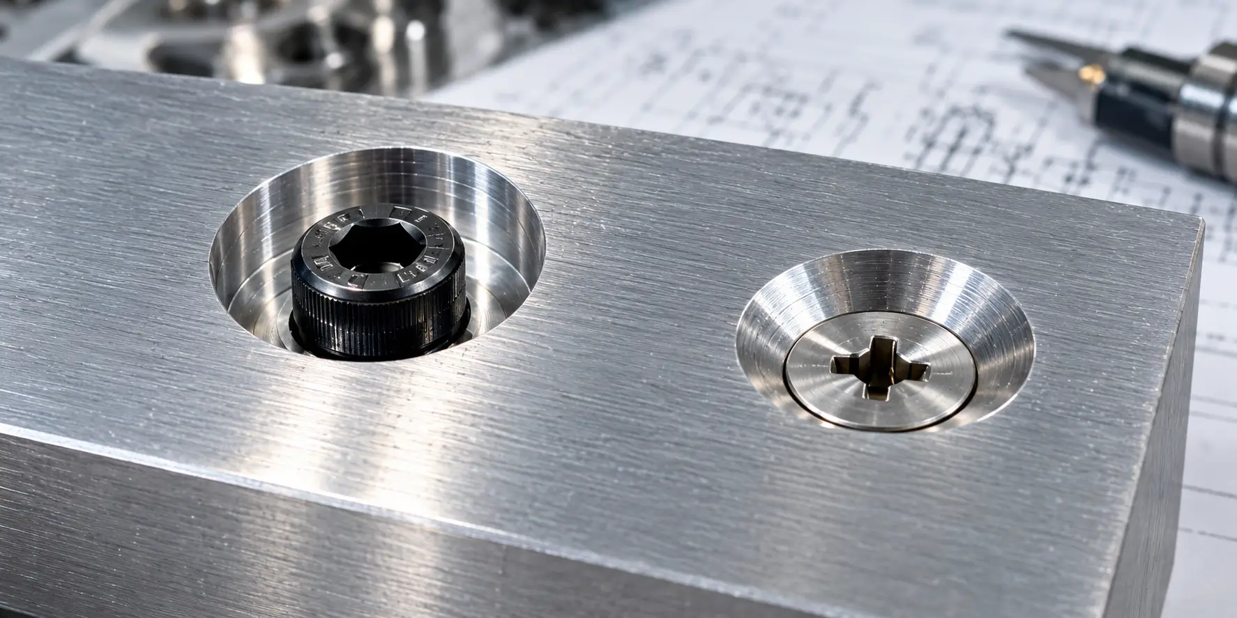
For most parts, the first choice comes from the screw being used. The more important question is whether the finished recess will allow that screw to seat correctly during assembly. Recess diameter, depth, angle, surrounding material, and machining access can all affect the final result even when the basic clearance hole is correct.
Counterbore vs Countersink: Quick Comparison
The easiest way to understand counterbore vs countersink is to look at the underside of the fastener head. A cylindrical head with a flat bearing surface normally needs a flat seat. A tapered head needs a matching conical seat.
| Feature | Counterbore | Countersink |
|---|---|---|
| Recess shape | Cylindrical | Conical |
| Seating surface | Flat | Tapered |
| Common fastener | Socket head cap screw | Flat-head screw |
| Main dimensions | Diameter and depth | Major diameter and included angle |
| Typical head position | Flush or below surface | Usually flush |
| Main purpose | Recess a cylindrical head | Seat a tapered head |
The basic geometry is simple. Problems usually start when the recess dimensions do not match the actual fastener or the assembly condition.
What Is a Counterbore?
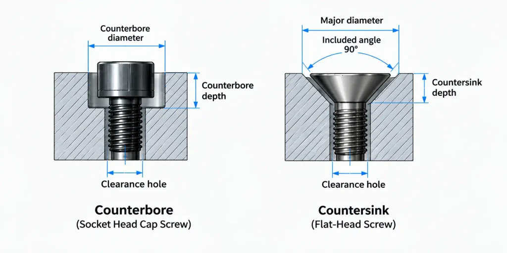
A counterbore is a cylindrical, flat-bottomed recess machined around a smaller hole. The smaller hole normally provides clearance for the screw shank or leads into a threaded feature, while the larger recess provides room for the fastener head. The term is also written as counter bore, and the finished feature may be described as a counterbore hole or counterbored hole.
Socket head cap screws are commonly used with counterbores because their cylindrical heads fit inside the recess and their flat bearing surfaces seat against the counterbore floor. Counterbore diameter provides clearance around the head, while counterbore depth determines where the head finishes relative to the surrounding surface.
The recess should be sized from the actual fastener head dimensions and required assembly clearance, not from the nominal thread size alone. Two screws with the same thread size can still have different head dimensions or under-head geometry.
What Is a Countersink?
A countersink is a conical recess at the entrance of a hole. It is normally used with a flat-head or other countersunk fastener whose underside has a compatible taper. When the two geometries match, the head can finish flush with or slightly below the surrounding surface.
A countersunk hole should not be confused with a small chamfer used only for deburring. A deburring chamfer removes the sharp edge around a drilled hole. A functional countersink hole forms part of the fastener seat, so its major diameter and included angle affect where the screw head finally sits.
This is the practical countersink meaning in an assembly. The taper is not simply an edge treatment. It is the surface that supports the tapered fastener head.
How to Choose Between a Counterbore and Countersink
Start with the fastener head. A socket head cap screw has a cylindrical head and flat bearing surface, so a counterbore is normally used when that head needs to sit inside or below the part surface. A flat-head screw has a tapered underside and normally requires a countersink with a compatible angle.
The required head position then determines how the recess should be sized. On a fixture plate, a socket head screw may only need to sit below a moving carriage. Once enough clearance is available, machining the counterbore deeper does not improve the assembly. A cover plate may have a different requirement if another component needs to sit directly against the outside face.
Part thickness alone is not a reliable selection rule. A thick housing can still have very little material below a recess because of an internal pocket, while a thinner part may have enough local material for a correctly sized recess. The fastener and the geometry around the actual hole should be considered together.
How Recess Geometry Affects Fastener Assembly
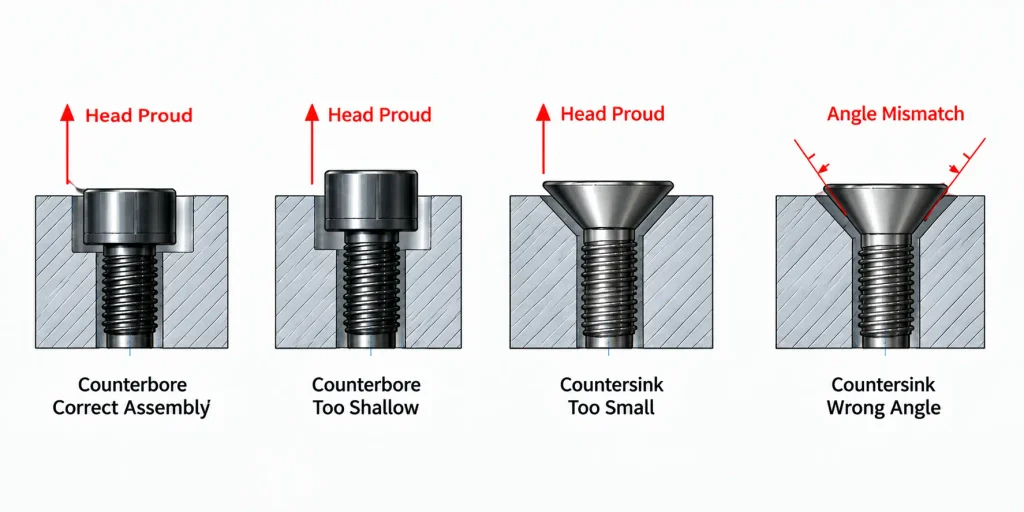
A recessed screw can pass through the clearance hole and still fail to seat correctly. In a counterbored hole, an undersized counterbore can allow the screw shank to pass while the head contacts the sidewall before reaching the flat seat. If the counterbore is too shallow, the screw can tighten normally while the head remains above the surrounding surface.
The counterbore floor can introduce another less obvious interference. When the feature is machined with an end mill, a radius may remain where the wall meets the floor. If that radius contacts the transition beneath the screw head before the flat bearing surface reaches the seat, the fastener may not sit as expected even though the basic diameter and depth look correct.
Countersinks fail in a different way. An undersized countersink leaves a flat-head screw proud of the surface, while a larger countersink allows the head to sit farther into the part. For an ideal 90° countersink, increasing the major diameter by 0.20 mm changes the axial cone position by about 0.10 mm. The clearance hole can remain unchanged while the final screw-head height moves.
The included angle matters as well. A screw intended for a 90° seat should not simply be installed in an 82° countersink because the opening is large enough. The screw may enter the recess, but the tapered surfaces will not contact as intended.
The useful distinction is simple: the clearance hole controls whether the screw shank can pass, while the recess controls whether the screw head can seat correctly.
How Recess Depth Affects Local Material Thickness
A recess can remove much more local material than the overall part thickness suggests.
Consider a 20 mm thick aluminum housing with an 8 mm deep pocket machined from the underside. If a 9 mm deep counterbore is placed directly above that pocket, the material remaining between the two features is only:
20 − 8 − 9 = 3 mm
If a 7 mm counterbore already places the screw safely below the required surface, increasing the depth to 9 mm removes another 2 mm from the local floor without improving the assembly.
The same issue can appear above cross holes, internal cavities, side pockets, or stepped internal features. The useful design check is therefore not simply whether the part is thick enough, but how much material remains at the actual recess location after machining.
How to Read Counterbore and Countersink Callouts
A drawing symbol identifies the type of recess, but the dimensions around it tell manufacturing how the fastener is expected to fit.
Counterbore Callout
The commonly used counterbore symbol, also searched as the counter bore symbol, is:
⌴
An illustrative counterbore callout could be:
Ø6.5 THRU ⌴ Ø11.0 × 7.0 DEEP
In this example:
Ø6.5 THRUdefines screw-shank clearance.⌴ Ø11.0defines the counterbore diameter and head clearance.7.0 DEEPlocates the flat seating surface.
Suppose the actual screw head is close to Ø10 mm. An Ø11 mm counterbore gives approximately 0.5 mm of nominal radial clearance per side before fastener and machining tolerances are considered.
This is also why counterbore diameter and depth should not be treated as interchangeable adjustments. Increasing diameter creates more space around the head, while increasing depth changes where the head finishes and removes more material below the recess.
Countersink Callout
The commonly used countersink symbol, also searched as the counter sink symbol, is:
⌵
An illustrative countersink callout could be:
Ø6.5 THRU ⌵ Ø12.0 × 90°
Here:
Ø6.5 THRUdefines screw-shank clearance.Ø12.0defines the countersink major diameter.90°defines the included angle of the tapered seat.
These values should be checked again if the fastener changes during the project. Two screws with the same nominal thread size can use different head geometry or seating angles.
Countersink Angle
There is no single countersink angle for every fastener. 82°, 90°, and 100° are used in different fastener systems.
The practical rule is to select the fastener first and specify the countersink angle required by that fastener. Increasing the countersink diameter does not correct an angle mismatch.
CNC Machining Problems with Counterbores and Countersinks
A hole can be easy to drill and still be difficult to counterbore.
Suppose a Ø6.5 mm hole center is 10 mm from a vertical wall. The drill has plenty of clearance. If the same hole requires an Ø18 mm counterbore, the recess radius is 9 mm, leaving only about 1 mm between the counterbore edge and the wall.
At that point, the hole centerline is no longer the main machining constraint. The cutter body, shank, and holder also need room around the recess. Inside a deep pocket, the cutting edge may reach the feature while the holder approaches the surrounding wall before the counterbore is finished.
Countersinks have a different process sensitivity. Their finished major diameter is often controlled by cutter penetration. After a tool replacement, regrind, or offset adjustment, the same programmed Z position does not necessarily produce exactly the same finished countersink if the effective tool geometry has changed.
That difference may be insignificant for a simple deburring chamfer. It matters more when the finished screw head needs to remain consistently flush with the surrounding surface.
How to Inspect Counterbored and Countersunk Holes
Counterbore inspection should separate the functions of the different dimensions. The smaller hole diameter confirms that the screw shank can pass. The counterbore diameter confirms that the head has enough clearance. Counterbore depth confirms the location of the flat seat and helps determine the final head position.
For a countersink, the clearance hole still controls shank clearance, but it does not verify the tapered seat. The countersink major diameter and included angle describe the geometry that controls how the flat-head screw seats.
A part can therefore pass a basic hole measurement and still create an assembly problem. If head position is function-critical, inspection should include the feature that controls that position rather than only the easiest diameter to measure.
Optimize Your Next Assembly
Counterbores and countersinks are straightforward when the fastener, recess dimensions, and surrounding part geometry agree. Problems usually appear when head clearance, seating depth, countersink angle, or local material around the recess has not been reviewed before machining.
ZH Precision provides CNC machining for custom mechanical parts with counterbored, countersunk, threaded, and other precision hole features. CAD models and drawings can be reviewed before quotation to identify potential issues involving fastener seating, recess geometry, tool access, and inspection requirements.
Conclusion
The basic counterbore vs countersink difference comes from the fastener head. A counterbore provides a cylindrical recess and flat seat, while a countersink provides a conical seat for a tapered head.
The more important question is whether the finished recess allows the fastener to assemble as intended. Selecting the screw first, defining the required head position, checking the local material, and controlling the dimensions that affect seating helps prevent a simple recessed hole from becoming an assembly problem.
FAQ
A counterbore is cylindrical with a flat seating surface, while a countersink is conical. Counterbores are commonly used with socket head cap screws, while countersinks are commonly used with flat-head screws.
Countersunk means that a tapered recess has been created so a compatible fastener head can sit within or flush with the surrounding surface.
Not necessarily. A chamfer may only remove a sharp edge or burr. A functional countersink is dimensioned to form the seating surface for a fastener head.
No. 82°, 90°, and 100° are used in different fastener systems. The fastener specification should determine the required angle.
Socket head cap screws are commonly used because their cylindrical heads fit inside the recess and their flat bearing surfaces seat against the counterbore floor.




