

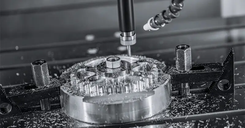
Rapid CNC prototyping provides a practical way to produce functional metal and engineering plastic parts for engineering validation while keeping development moving. This guide explains when CNC prototyping is most useful, what affects cost and lead time, how DFM can reduce manufacturing risk, and what information is needed to move from prototype design to quotation and production.
What Is Rapid CNC Prototyping?
Rapid CNC prototyping is the use of CNC machining to produce functional prototype parts directly from CAD data within a short development cycle. Unlike visual models, CNC prototypes can be made from engineering metals and plastics, allowing engineers to evaluate dimensions, fit, assembly, mechanical performance, and other requirements under conditions closer to the final product.
The speed of CNC prototyping depends on more than machine availability. Part geometry, material, tolerance requirements, tool access, setup complexity, inspection, and surface finishing all influence how quickly a design can become a finished part. Designs that account for these manufacturing factors early are easier to machine, require fewer adjustments, and move through prototype iterations faster.
When Does Rapid CNC Prototyping Make Sense?
Rapid CNC prototyping is most valuable when a prototype must do more than confirm appearance. Parts used for fit checks, assembly trials, functional testing, or mechanical evaluation often need realistic material properties, accurate interfaces, threaded features, precision bores, and other details that closely represent the final component.
It is also useful when design decisions depend on how a real machined part behaves. A housing may need to align with mating components, a shaft may require a controlled fit, or a bracket may need to withstand actual loads during testing. Producing these features in production-relevant metals or engineering plastics gives engineers more reliable feedback before the design moves into further validation or production.
What Does the Prototype Need to Validate?
Before machining begins, define what the prototype is expected to prove. A rapid CNC prototype does not need every feature controlled to the same level. The machining and inspection requirements should follow the specific function being validated.
| Validation Goal | What to Check |
| Fit and Assembly | Mating dimensions, hole locations, alignment, clearance, and interference |
| Critical Dimensions | Precision bores, locating features, datums, and dimensions that affect function |
| Mechanical Performance | Strength, stiffness, deformation, and load-bearing features |
| Threads and Interfaces | Thread fit, inserts, fasteners, sealing features, and mating surfaces |
| Material Performance | Flatness, surface contact, groove geometry, sealing interfaces, and critical mating faces |
| Material Performance | Whether the selected material behaves correctly under the intended test conditions |
| Functional Surfaces | Surface finish, contact areas, sliding surfaces, and other function-critical features |
Once the validation target is clear, tighter tolerances, material requirements, and inspection effort can be concentrated on the features that actually affect the test. Non-critical geometry does not need to carry the same manufacturing requirements.
How Does Rapid CNC Prototyping Work?
Rapid CNC prototyping follows a structured CNC machining process, moving through four stages from design review and process planning to machining, inspection, and a tested physical part.
Step 1: Review the Design and Requirements. The latest CAD model, drawing, material, critical dimensions, quantity, finish, and prototype validation goals are reviewed first to establish what the part needs to achieve.
Step 2: Complete DFM, Programming, and Setup Planning. The design is checked for manufacturability, then the machining process, toolpaths, workholding, setups, and inspection requirements are planned before cutting begins.
Step 3: Machine and Finish the Part. Raw material is machined into the required geometry, followed by deburring, surface finishing, or other secondary operations specified for the prototype.
Step 4: Inspect, Test, and Revise the Prototype. Critical dimensions and functional features are verified before the prototype is used for fit, assembly, or performance testing. Test results can then be used to refine the design before the next iteration or production release.
For faster iterations, ZH Precision provides CNC prototyping support from DFM review through machining and inspection. Explore our CNC prototyping services for materials, tolerances, and project capabilities.
What Affects Rapid CNC Prototyping Cost and Lead Time?
Rapid CNC prototyping can move quickly from CAD to a functional part, but CNC machining cost and lead time still depend on how demanding the prototype is to manufacture. Two parts of similar size can require very different machining time when geometry, material, tolerances, setups, finishing, or inspection requirements change.
| Factor | Effect on Cost and Lead Time |
| Part Geometry | Deep pockets, complex contours, undercuts, and multi-sided features can require more machining time and additional setups. |
| Material | Easy-to-machine materials generally reduce cutting time, while harder alloys may require slower machining and greater tool control. |
| Tolerance Requirements | Tight tolerances can add finishing passes, setup control, and inspection time. |
| Number of Setups | Additional orientations increase setup, alignment, and machining time. |
| Surface Finishing | Anodizing, plating, polishing, painting, or other secondary processes extend the total lead time. |
| Inspection Requirements | CMM reports, FAI, or detailed dimensional verification require additional inspection work. |
| Quantity | Programming and setup costs are concentrated in one-off prototypes but spread across more parts as quantity increases. |
For rapid CNC prototypes, the goal is not to remove every manufacturing requirement. It is to define which requirements are necessary for prototype validation and avoid adding precision, finishing, or inspection that does not contribute to the test.
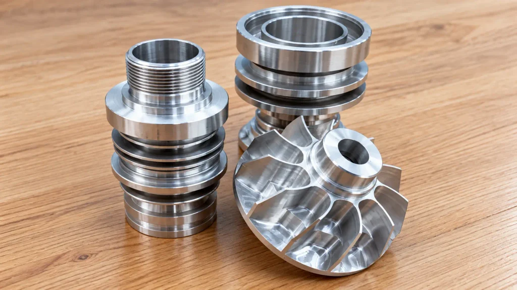
DFM Considerations for Rapid CNC Prototypes
DFM review helps identify design features that can slow machining, increase cost, or create unnecessary prototype risk. For rapid CNC prototyping, the goal is to improve manufacturability while preserving the features the prototype actually needs to validate.
1. Check Tool Access. Cutting tools need sufficient access to pockets, recessed surfaces, side features, and internal geometry. Restricted access can require longer tools, extra orientations, or slower cutting conditions.
2. Use Practical Radii and Pocket Depths. Small internal radii require smaller cutters, while deep narrow pockets increase tool overhang and machining difficulty. More accessible geometry generally allows faster and more stable cutting.
3. Maintain Stable Wall Thickness. Thin walls and unsupported sections can deflect during machining or move after material removal. Wall thickness should provide enough rigidity without compromising the prototype’s functional requirements.
4. Apply Tight Tolerances Selectively. Close tolerances should be reserved for fits, alignment features, sealing surfaces, bearing locations, and other dimensions that directly affect prototype validation.
5. Consider Setup and Datum Relationships. Features with important positional relationships should use practical datum references and machining orientations. Reducing unnecessary repositioning helps maintain feature-to-feature accuracy.
6. Specify Surface Finish Where It Matters. Controlled roughness or cosmetic finishing should be limited to surfaces where function or appearance requires it. Unnecessary finish requirements add processing time and cost.
A useful DFM review does not simplify the part blindly. It identifies where design flexibility exists so machining effort can stay focused on the features that matter most during prototype testing.
What Do You Need for a Rapid CNC Prototype Quote?
A clear RFQ reduces clarification time and helps the supplier prepare an accurate quotation and realistic lead time. For rapid CNC prototypes, the key information is the latest design files, material, quantity, critical requirements, finish, and required delivery date. See the CNC Prototype RFQ Guide for a more detailed breakdown of the information needed for quotation.
Submit a 3D CAD Model and Drawing
A complete set of design files helps the supplier understand the part correctly and reduces clarification before quotation.
Latest 3D CAD Model. Provide the current STEP, Parasolid, or other accepted solid model to define the nominal part geometry.
Controlled 2D Drawing. Include critical tolerances, GD&T, threads, datums, surface requirements, and inspection notes that cannot be communicated through the 3D model alone.
Consistent Revision. Make sure the CAD model and drawing carry the same revision so the supplier is reviewing the correct design.
Critical Features. Identify the fits, interfaces, dimensions, and functional features that the prototype must validate.
Choose the Material Based on the Test
Select the material according to what the prototype needs to validate. Fit and assembly checks may allow a more machinable alternative, while strength, temperature, corrosion, wear, or other functional testing usually requires the intended production material or a close equivalent.
When material performance matters, specify the actual grade rather than simply writing aluminum, steel, or plastic. Material grade can affect machining time, cost, availability, and how accurately the prototype represents the final part.
Define the Complete RFQ Scope
| Information | Why It Matters |
| 3D CAD and drawing | Defines geometry and critical requirements |
| Material and quantity | Affects machining, cost, and lead time |
| Critical tolerances | Identifies features requiring tighter control |
| Surface finish | Adds machining or secondary processing |
| Required date | Defines the project schedule |
Keep tight tolerances focused on the features the prototype actually needs to validate. This avoids unnecessary machining and inspection while giving the supplier enough information to quote the project accurately.
How to Evaluate a Rapid CNC Prototyping Supplier
A rapid CNC prototyping supplier should be evaluated on more than unit price or promised lead time. The technical review should show that the supplier understands the part, while the quotation should clearly define the manufacturing scope before the order is placed.
Evaluate the Technical Review
A useful technical review should confirm whether the supplier has understood the main engineering and production requirements of the prototype.
Machining approach: Which CNC process fits the geometry
Critical features: Which dimensions, fits, and interfaces require closer control
Material and finish: Whether the specified requirements are clearly understood
Inspection: Which features need verification and what reports are required
Lead time: Whether the requested schedule is realistic for the complete scope
The review should be specific to the actual part rather than a generic statement that the design is machinable.
Compare the Complete Quotation Scope
Price comparisons only make sense when suppliers are quoting the same work. Check what is included before comparing the final number.
Material: Grade, condition, and material cost
Machining: CNC operations included in the quotation
Finishing: Any required secondary or surface treatments
Inspection: Measurement, reports, or certificates included
Lead time: The complete schedule through finished parts
Delivery: Packaging, shipping terms, and additional charges
A quotation that clearly defines these items makes it easier to compare suppliers and reduces unexpected cost or schedule changes after the project starts.
Conclusion
Rapid CNC prototyping is most effective when the prototype has a clear validation purpose and the manufacturing requirements are defined before machining begins. Material selection, tolerances, part geometry, finishing, inspection, and supplier review all influence how quickly a CAD design can become a functional part.
The goal is not simply to machine a prototype as fast as possible, but to obtain a part that provides useful engineering feedback without unnecessary cost or delay. A well-planned CNC prototype can shorten design iterations, reduce manufacturing uncertainty, and provide a stronger foundation for the transition into production.




