

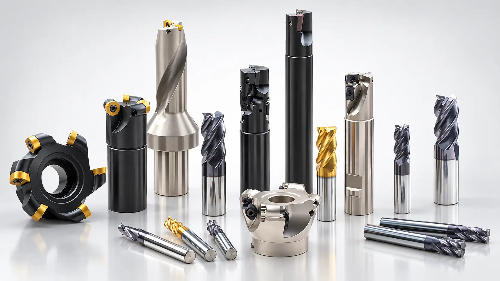
This guide introduces seven common tool types, explains their machining uses and suitable materials, and covers the basics of tool selection and cutting speeds and feeds.
What Are CNC Milling Tools?
CNC milling tools are rotating cutters that remove material from a workpiece. Their cutting edges shape flat surfaces, slots, pockets, and curved contours as the machine moves the tool and workpiece along a programmed path. The cutter’s shape and dimensions determine which features it can reach and the geometry it leaves behind.
An end mill cuts with edges along its sides and tip, while a face mill primarily machines broad, flat surfaces. CNC machining centers also use drills to create holes and taps to cut internal threads, allowing milling, drilling, and tapping operations to be completed on the same machine.
7 Common CNC Milling Tools and Their Uses
CNC machining centers use different cutting tools to produce flat surfaces, pockets, curved contours, holes, and threads. The following seven tool types cover common machining tasks, with guidance on their applications, suitable materials, and practical limitations.
1. Flat End Mills
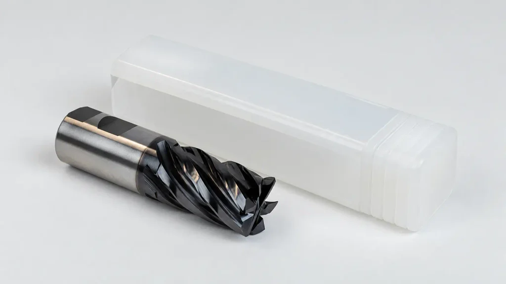
Flat end mills have a flat cutting tip and cutting edges along their sides. They machine straight walls and flat floors, making them a common choice for pockets, slots, and stepped features.
Suitable Applications: Slotting, pocket milling, shoulder milling, and external profiling. In a machined housing, a flat end mill can remove material from the cavity, finish its walls, and cut steps for a mating cover.
Suitable Materials: Aluminum, steel, stainless steel, brass, cast iron, and engineering plastics, using cutter geometries and coatings suited to the material. Fewer flutes provide more room for chip evacuation, while higher flute counts can suit finishing passes with lighter radial engagement.
Usage Considerations: Tool diameter determines the smallest internal corner radius that can be produced inside a pocket. Smaller cutters reach tighter corners but are less rigid. For deep pockets, use the shortest tool reach that provides sufficient clearance to reduce deflection and chatter.
2. Ball Nose End Mills
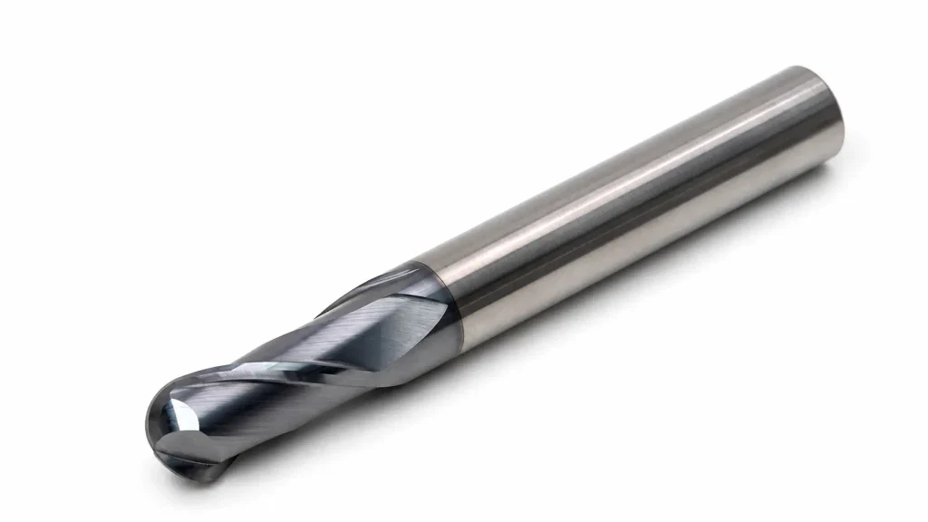
Ball nose end mills have a rounded cutting tip that follows curved surfaces and three-dimensional contours. They are commonly used for finishing shapes that a flat end mill cannot follow smoothly.
Suitable Applications: Contour finishing, mold and die cavities, sculpted surfaces, and curved transitions. For example, a ball nose end mill can follow the curved profile of a mold cavity after roughing removes most of the material.
Suitable Materials: Aluminum, steel, stainless steel, hardened tool steel, and engineering plastics, with tool grades and coatings selected for the material and its hardness.
Usage Considerations: The spacing between adjacent passes, known as stepover, affects the height of the ridges left on the surface. A smaller stepover produces finer ridges but increases machining time. Cutting speed also decreases toward the center of the rounded tip, so tool contact position matters when finishing shallow surfaces.
3. Corner Radius End Mills
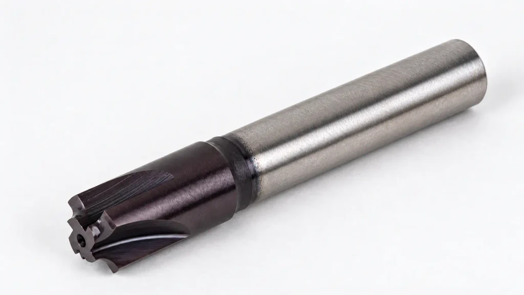
Corner radius end mills, also called bull nose end mills, have a flat cutting end with rounded corners. This geometry provides support at the cutting corners and produces a rounded transition where a pocket floor meets its walls.
Suitable Applications: Pocket roughing, shoulder milling, flat-floor machining, and producing bottom fillets. A pocket requiring a flat base with rounded floor-to-wall transitions is a typical application.
Suitable Materials: Aluminum, steel, stainless steel, cast iron, and tool steel, using cutter geometries and coatings suited to the material and its hardness.
Usage Considerations: The cutter’s corner radius must fit the fillet specified on the drawing. A larger radius leaves excess material at the floor-to-wall transition, while a smaller radius may require additional passes to create the specified shape. Use the shortest practical tool reach to limit deflection when machining deep pockets.
4. Face Mills
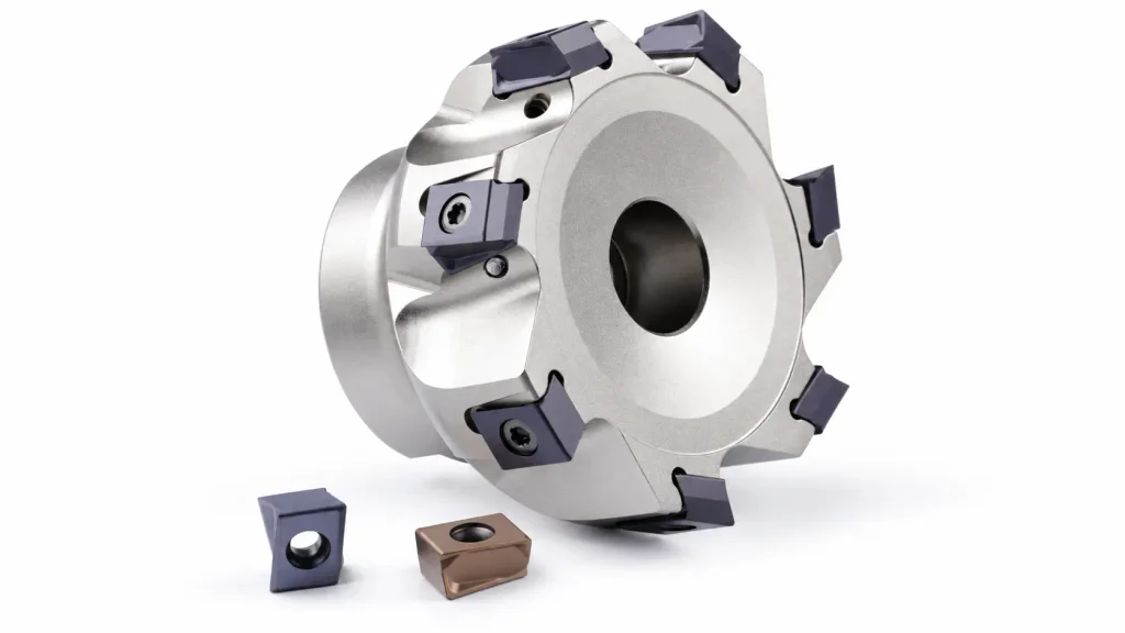
Face mills use cutting edges arranged around a relatively large cutter body to machine flat surfaces. Many designs hold replaceable carbide inserts, allowing worn cutting edges to be indexed or replaced without replacing the entire tool.
Suitable Applications: Facing blocks, plates, mounting surfaces, and other broad, accessible areas. Their wide cutting diameter can cover a surface in fewer passes than a smaller end mill.
Suitable Materials: Steel, stainless steel, aluminum, cast iron, and tool steel, with insert grades and cutting geometries selected for the material and its hardness.
Usage Considerations: Cutter diameter should suit the surface width and the machine’s power and rigidity. A larger face mill is not always more efficient if it causes vibration or exceeds available spindle power. Insert condition, cutter runout, and chip evacuation also affect the finish, particularly where chips may be cut again.
5. Drill Bits
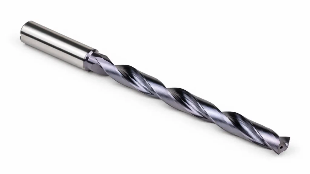
Drill bits create cylindrical holes by cutting into a workpiece along their axis. Twist drills are a common choice, with helical flutes that carry chips out of the hole during machining.
Suitable Applications: Through holes, blind holes, clearance holes for fasteners, and pilot holes for tapping, boring, or reaming. Drilling often creates the initial hole before another tool brings it to the required size or finish.
Suitable Materials: Aluminum, steel, stainless steel, cast iron, brass, and engineering plastics. Drill material, point geometry, and coating should suit the workpiece; high-speed steel and carbide are common options.
Usage Considerations: Hole depth affects chip evacuation and coolant access. Deep holes may require a suitable peck-drilling cycle or a through-coolant drill, depending on the tool and material. A standard drill leaves a conical bottom in a blind hole, so the programmed depth must account for the drill point when a specified full-diameter depth is required.
6. Taps
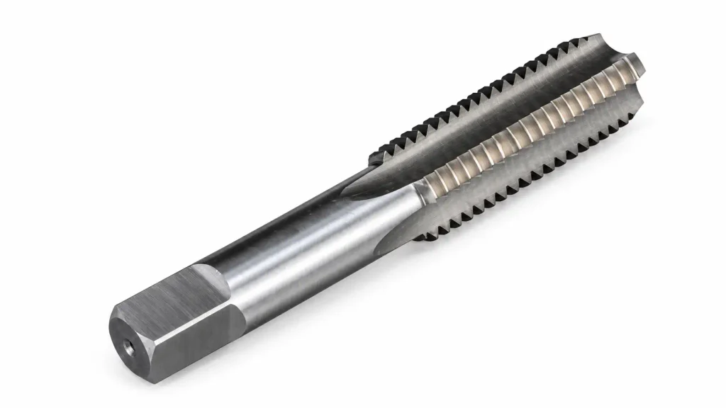
Cutting taps produce internal threads in pre-drilled holes. Their cutting teeth follow the specified thread profile, while flutes provide space for chips to leave the cutting area.
Suitable Applications: Threaded mounting holes in housings, brackets, plates, and machine components. The tap must match the required thread standard, diameter, and pitch.
Suitable Materials: Steel, stainless steel, aluminum, brass, cast iron, and engineering plastics, using tap geometries and coatings selected for the material. Spiral point taps commonly push chips forward through a through hole, while spiral flute taps draw chips back toward the entrance of a blind hole.
Usage Considerations: The drilled hole diameter affects tapping torque and thread engagement. A hole that is too small increases the risk of tap breakage, while an oversized hole can produce insufficient thread engagement. Blind holes also need clearance below the required thread depth for the tap’s chamfered lead and chips. During tapping, axial feed must match spindle rotation and thread pitch.
7. Chamfer Mills
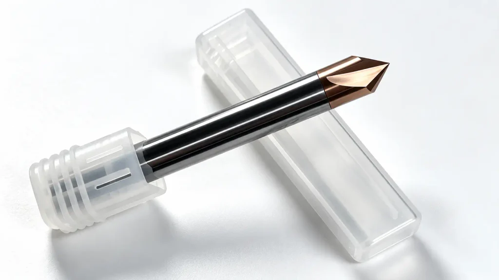
Chamfer mills have angled cutting edges that create beveled edges on a part. They are commonly used to remove sharp corners and produce chamfers specified on a drawing.
Suitable Applications: Edge chamfering, hole-entry chamfering, and deburring around machined profiles. A chamfer at a hole entrance can help guide a fastener, while a chamfer along an exposed edge removes a sharp corner.
Suitable Materials: Aluminum, steel, stainless steel, brass, cast iron, and engineering plastics, with cutting geometries and coatings suited to the material.
Usage Considerations: Select the cutter angle to match the required chamfer. A tool with a 90° included angle typically produces a 45° chamfer when its axis is perpendicular to the surface. Cutting depth controls chamfer size, so tool positioning and existing burrs affect consistency. Check the usable cutting diameter, particularly around small holes where the tool tip may have limited cutting capability.
How to Choose the Right CNC Milling Tool
Start with the feature being machined. A broad, open surface may suit a face mill, while a narrow slot requires an end mill small enough to enter it. Curved surfaces often need a ball nose cutter, and a specified floor-to-wall radius may suit a bull nose end mill. Check access as well as shape: the cutter and holder must reach the feature without contacting nearby walls or fixtures.
Workpiece material helps determine the cutting-edge geometry, tool material, and coating. Aluminum machining benefits from sufficient chip space and cutting edges designed to limit material buildup. Hardened steel requires a tool rated for its hardness. Use the tool manufacturer’s material recommendations to narrow the selection rather than choosing by cutter shape alone.
Choose the largest practical cutter that fits the feature, with the shortest reach that provides clearance. A small diameter or long overhang reduces rigidity and can increase deflection. For a deep pocket with tight internal corners, a larger tool can remove most of the stock before a smaller cutter finishes the remaining areas.
Roughing and finishing may also require different tools or cutting conditions. Roughing prioritizes material removal and chip evacuation; finishing uses controlled passes to achieve the required dimensions and surface finish. A tool that removes stock efficiently may not be the best choice for the final pass on a thin wall or detailed contour.
CNC Milling Tool Speeds and Feeds
Spindle speed and feed rate work together, but they describe different movements. Spindle speed is the tool’s rotation rate in revolutions per minute (RPM). Feed rate is how quickly the tool advances through the material, usually expressed in millimeters per minute (mm/min).
Start with the tool manufacturer’s recommended cutting speed and feed per tooth for the workpiece material. Cutting speed describes the speed of the cutting edge at the effective cutting diameter. Feed per tooth describes how far the tool advances for each cutting tooth.
For milling cutters, the basic metric calculations are:
| Parameter | Formula | Units |
| Spindle speed | n = (1,000 × Vc) ÷ (π × D) | RPM |
| Feed rate | Vf = fz × z × n | mm/min |
Here, Vc is cutting speed in m/min, D is cutting diameter in mm, fz is feed per tooth in mm/tooth, and z is the number of effective cutting teeth.
For a calculation example, assume a 10 mm end mill with three flutes, a cutting speed of 150 m/min, and a feed per tooth of 0.03 mm. The calculated spindle speed is approximately 4,775 RPM, giving a feed rate of approximately 430 mm/min. These assumed values illustrate the calculation; they are not a material-specific machining recommendation.
The starting values still need to suit the operation. Full-width slotting, deep pockets, and long tool overhang create different cutting conditions from a light finishing pass. Ball nose cutters also require attention to the effective cutting diameter at the contact point. Drilling typically uses feed per revolution, while tapping requires axial feed synchronized with spindle speed and thread pitch.
Conclusion
Choosing CNC milling tools starts with the features on the drawing. Face mills machine broad surfaces, end mills produce pockets and profiles, and ball nose cutters follow curved contours. Drills, taps, and chamfer mills complete holes, threads, and beveled edges.
After selecting the tool type, check its diameter, reach, and suitability for the workpiece material. Use the manufacturer’s cutting data to calculate starting speeds and feeds, then adjust for cutting engagement, chip evacuation, and machining stability.




