

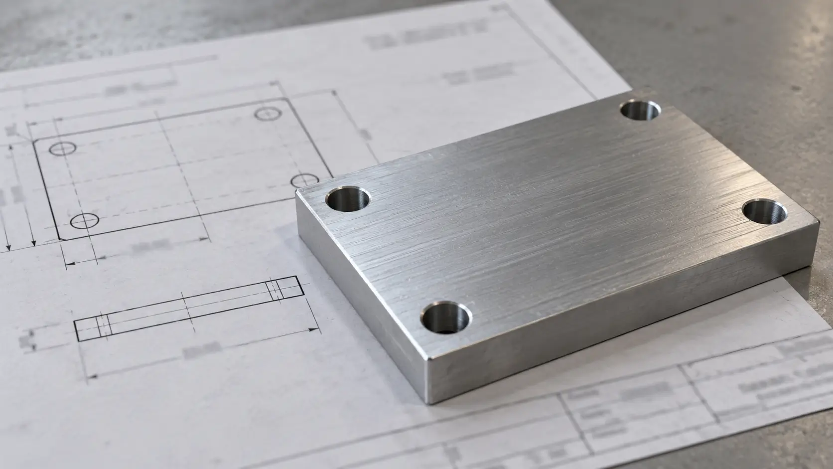
A hole can meet its diameter tolerance yet sit in the wrong position, preventing a bolt from passing through mating components. GD&T describes these geometric requirements alongside size tolerances. This guide explains its basic principles, common symbols, and how drawing requirements influence CNC machining and inspection.
What Is GD&T?
GD&T stands for Geometric Dimensioning and Tolerancing. It specifies how much a feature may deviate from its intended shape, orientation, or location. Each geometric requirement defines a tolerance zone within which the controlled surface, axis, or other geometric element must lie.
On a CNC part drawing, a diameter tolerance specifies the acceptable size of a hole. A position tolerance controls where its axis may lie, while a flatness tolerance limits variation across a surface. These requirements address different aspects of the part and establish measurable acceptance criteria.
Drawings commonly reference ASME Y14.5 or ISO 1101, with additional ISO GPS standards supporting requirements such as datums and material conditions. Although many symbols look similar, the rules are not identical. The standard and edition identified on the drawing determine how its requirements should be interpreted.
How Does GD&T Work?
GD&T applies a geometric requirement to a specific feature through a drawing annotation. The symbol identifies the characteristic being controlled, the tolerance value defines the permitted variation, and datum references establish the measurement reference where required.
Reading the annotation involves understanding both the allowable variation and the geometry to which it applies.
Datums and Datum Reference Frames
A datum provides a theoretically exact reference for locating or orienting other features. It may be a plane, axis, or point established from an actual feature on the part.
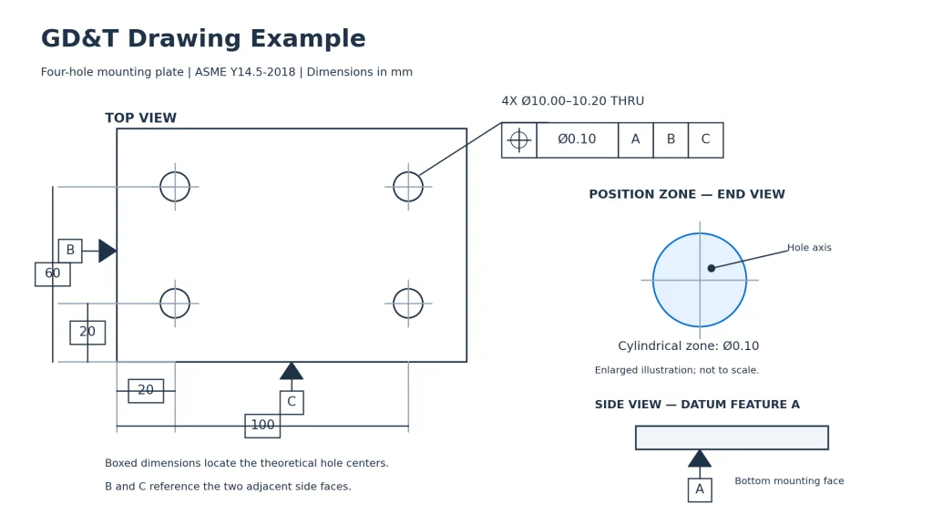
For example, a mounting plate’s bottom face may be identified as datum feature A, with two adjacent side faces identified as datum features B and C. These physical surfaces establish the references used to evaluate the hole pattern.
The physical surface and the datum derived from it are different. A machined face contains small imperfections; the datum plane established from that face is theoretically exact.
When a control references A, B, and C in that order, they serve as the primary, secondary, and tertiary references. This order determines how the datum reference frame is established. Changing the order can change the evaluation of the same feature.
Basic Dimensions and Tolerance Zones
Basic dimensions appear inside rectangular boxes on an ASME-based drawing. They specify theoretically exact values, such as the location of a hole center or the angle of a surface. The associated geometric tolerance defines the allowable variation.
Suppose basic dimensions locate a mounting hole, and its position control specifies ⌀0.10 mm relative to A, B, and C, without a material condition modifier. The requirement defines a cylindrical tolerance zone 0.10 mm in diameter at the specified location and orientation. The evaluated hole axis must remain within that zone.
A surface flatness requirement uses a different zone. A 0.05 mm flatness tolerance defines two parallel planes 0.05 mm apart, within which the entire controlled surface must lie. Surface flatness does not require a datum reference because it controls the surface’s form independently.
GD&T Symbols and Their Meanings
GD&T symbols fall into five categories: form, orientation, location, profile, and runout. Each category addresses a different geometric requirement.
Form controls describe the shape of a feature without datum references. Orientation controls establish its angular relationship to a datum. Position controls feature location and applicable orientation, while profile controls variation from a specified contour or surface. Runout controls surface variation during rotation about a datum axis.
The following table summarizes the geometric controls in ASME Y14.5-2018. The symbol graphics in the accompanying chart help identify their appearance on drawings.
| Category | Symbol | Geometric Control | What It Controls |
|---|---|---|---|
| Form | Straightness | Straightness of a line element or derived median line. | |
| Form | Flatness | Flatness of a surface or derived median plane. | |
| Form | Circularity | Roundness of individual circular cross-sections. | |
| Form | Cylindricity | Form of an entire cylindrical surface. | |
| Orientation | Parallelism | Parallel orientation of a surface or axis relative to a datum. | |
| Orientation | Perpendicularity | Orientation of a surface or axis at 90° to a datum. | |
| Orientation | Angularity | Orientation at a specified basic angle to a datum. | |
| Location | Position | Location of a feature, with orientation controlled where applicable. | |
| Profile | Profile of a Line | Variation from a specified profile within a cross-section. | |
| Profile | Profile of a Surface | Variation from a specified three-dimensional surface profile. | |
| Runout | Circular Runout | Surface variation at individual circular elements during rotation about a datum axis. | |
| Runout | Total Runout | Surface variation across the entire controlled surface during rotation about a datum axis. |
Concentricity and symmetry were removed from ASME Y14.5-2018. For older drawings or ISO-based requirements, follow the standard and edition specified on the drawing.
For CNC parts, frequently encountered applications include flatness on mounting faces, position on hole patterns, perpendicularity on bores, and runout on rotating surfaces. The correct control depends on the feature’s function.
Concentricity and symmetry appear on some older drawings but were removed from ASME Y14.5-2018. Their presence makes checking the specified standard and edition particularly important.
How to Read a Feature Control Frame
A feature control frame presents a geometric requirement in separate compartments. Reading from left to right, it contains the geometric characteristic symbol, tolerance value and associated modifiers, followed by datum references where required.
For a mounting hole, a position symbol followed by ⌀0.10 | A | B | C specifies a cylindrical position tolerance zone 0.10 mm in diameter relative to datums A, B, and C. The diameter symbol describes the tolerance zone, not the hole diameter.
Material condition modifiers can change how the requirement applies. A circled M after the tolerance value applies the requirement at maximum material condition (MMC). For a hole, MMC is its smallest permitted diameter; for a shaft, it is its largest permitted diameter.
Consider a hole with diameter limits of 10.00–10.20 mm and a position tolerance of ⌀0.10 mm at MMC. If its actual size is 10.15 mm, the departure from MMC is 0.15 mm. This provides 0.15 mm of bonus tolerance, bringing the available position tolerance to ⌀0.25 mm.
A circled L applies the requirement at least material condition (LMC). Under ASME rules, where applicable, the absence of either modifier means the geometric tolerance applies regardless of feature size (RFS).
The modifier’s placement matters. A circled M after a datum reference identifies a maximum material boundary requirement for that reference; it does not have the same role as a circled M after the geometric tolerance value.
Why Is GD&T Important in CNC Machining?
A machined mounting plate may have correctly sized holes but fail to align with the threaded holes in its mating component. Tightening the hole diameter tolerance would not correct a misplaced pattern. The drawing needs to control hole location relative to the features that locate the plate in the assembly.
Similar problems occur with mounting faces and rotating parts. A face may need a flatness requirement to limit gaps at the mating interface. A shaft’s bearing seat may need a runout requirement to limit surface variation during rotation. These functional needs cannot always be communicated adequately through size tolerances alone.
GD&T also helps allocate manufacturing effort. A mating surface may require close geometric control, while a non-mating outer surface can accept greater variation. Applying tolerances according to function avoids imposing equally tight requirements across the entire part.
Clear geometric requirements give machining and inspection teams a shared reference. The manufacturing team can plan setups around critical relationships, and the inspection team can evaluate the resulting features against the same drawing requirements.
How Are GD&T Requirements Applied to CNC Machined Parts?
Applying GD&T begins with understanding the drawing before selecting machining operations. Material, part geometry, datum features, tolerance values, and inspection access all affect the manufacturing approach.
A requirement that is practical for a rigid mounting block may be more difficult on a thin plate or deep housing. Reviewing these differences early helps identify where the process needs additional support, finishing operations, or clarification.
Drawing Review and Machining Planning
The initial review identifies the specified standard, datum references, critical features, and any requirements that need clarification. Missing basic dimensions, inconsistent datum references, or conflicting notes should be resolved before machining begins.
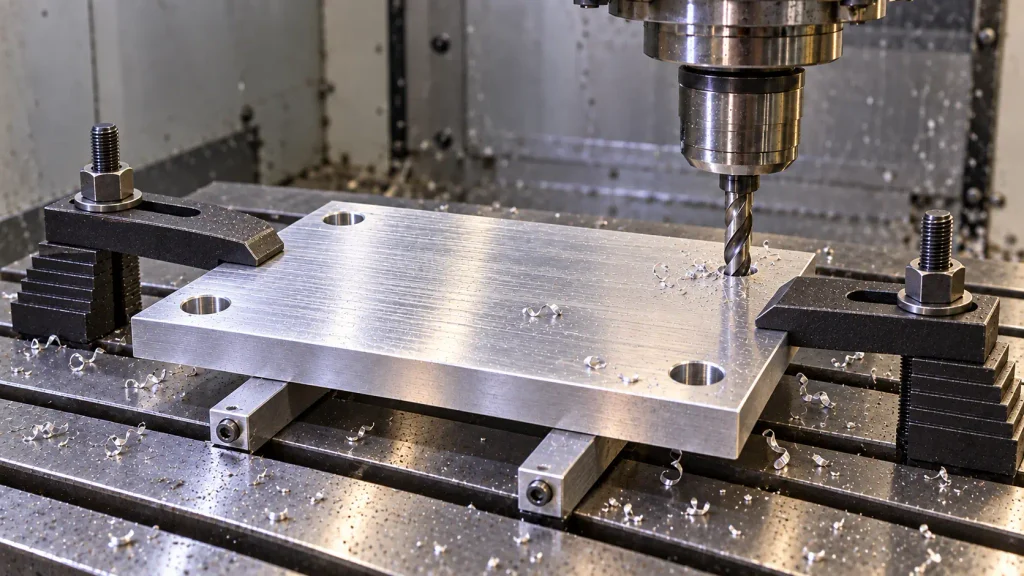
Datum features also influence machining sequence. If a hole pattern is controlled relative to a mounting face, the process must establish and preserve that relationship. Machining related features in one setup can reduce errors introduced by removing and repositioning the part.
Multiple setups may still be necessary. In that case, locating surfaces and fixtures need to support consistent transfer between operations. The drawing’s inspection datums inform this planning, although a machining fixture does not automatically reproduce the complete inspection datum reference frame.
Machining Critical Features
A four-hole mounting plate illustrates how separate requirements guide machining. Its holes have diameter limits of 10.00–10.20 mm, while basic dimensions locate their centers. A position tolerance of ⌀0.10 mm relative to A, B, and C, without a material condition modifier, controls the hole axes.
A hole measuring 10.10 mm passes the size requirement. It may still fail position if its evaluated axis extends outside the specified cylindrical tolerance zone. The process must therefore control both hole size and the pattern’s relationship to the reference features.
On other CNC parts, a precision bore may require boring or reaming to achieve its specified size and surface condition. A shaft may need a finishing operation to meet bearing-seat requirements. The appropriate operation depends on the material, geometry, tolerance, and available machining capability.
Thin components require particular attention to distortion. Clamping pressure can temporarily flatten a plate, allowing it to change shape after release. Support, cutting sequence, and stock removal must account for this behavior rather than relying on measurements taken only while the part is tightly clamped.
Inspection and Reporting
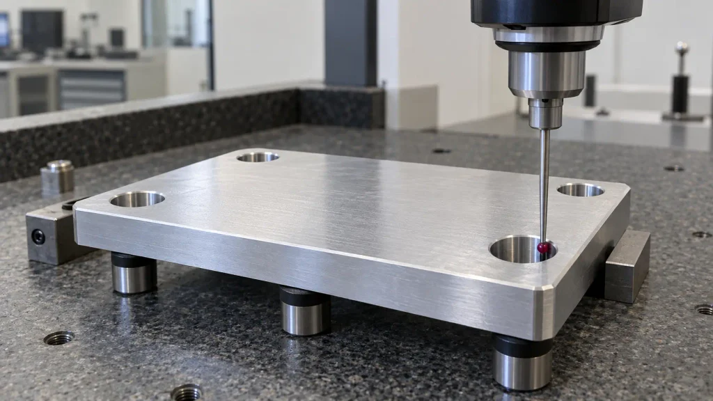
Inspection evaluates the requirement defined on the drawing. Hole diameter can be checked with suitable bore-measuring equipment, but hole position requires evaluation relative to the specified datum reference frame.
A CMM can measure hole patterns and many other geometric relationships. Surface plates with appropriate indicators can support flatness checks, while runout can be evaluated by rotating the part about an established datum axis and recording indicator variation.
Equipment selection depends on the tolerance, geometry, accessibility, and measurement uncertainty. A CMM is useful for many applications, but it is not the only suitable method for every geometric requirement.
Inspection reports should connect results to the relevant drawing features. Where applicable, they should identify the specified tolerance, datum references, measured result, and acceptance status. A diameter result alone does not demonstrate compliance with position, and a surface roughness measurement does not establish flatness.
CNC Machining Support for Parts with GD&T Requirements
ZH Precision supports CNC milling, turning, and 5-axis machining for parts with specified size and geometric requirements. Projects may include housings with locating bores, mounting plates with controlled hole patterns, brackets with mating faces, and shafts with bearing-seat requirements.
Before production, drawing review helps identify critical features and evaluate suitable machining and inspection methods. CMM and other dimensional inspection equipment support checks according to the agreed project requirements. Achievable tolerances depend on the material, feature dimensions, part rigidity, and manufacturing process.
For a project evaluation, provide the CAD file, dimensioned drawing, material, quantity, and inspection requirements. Identify any particularly important mating features or reporting needs so they can be considered during process planning and quotation.
Conclusion
GD&T defines geometric requirements that size tolerances alone may not fully describe. On a CNC drawing, it can specify how flat a mounting face must be, where a hole axis may lie, or how a rotating surface may vary relative to a datum axis.
Understanding these requirements involves reading the symbol, tolerance zone, modifiers, and datum references together. Clear specifications help manufacturers plan suitable machining setups and inspection methods, allowing each critical feature to be evaluated against the drawing.




