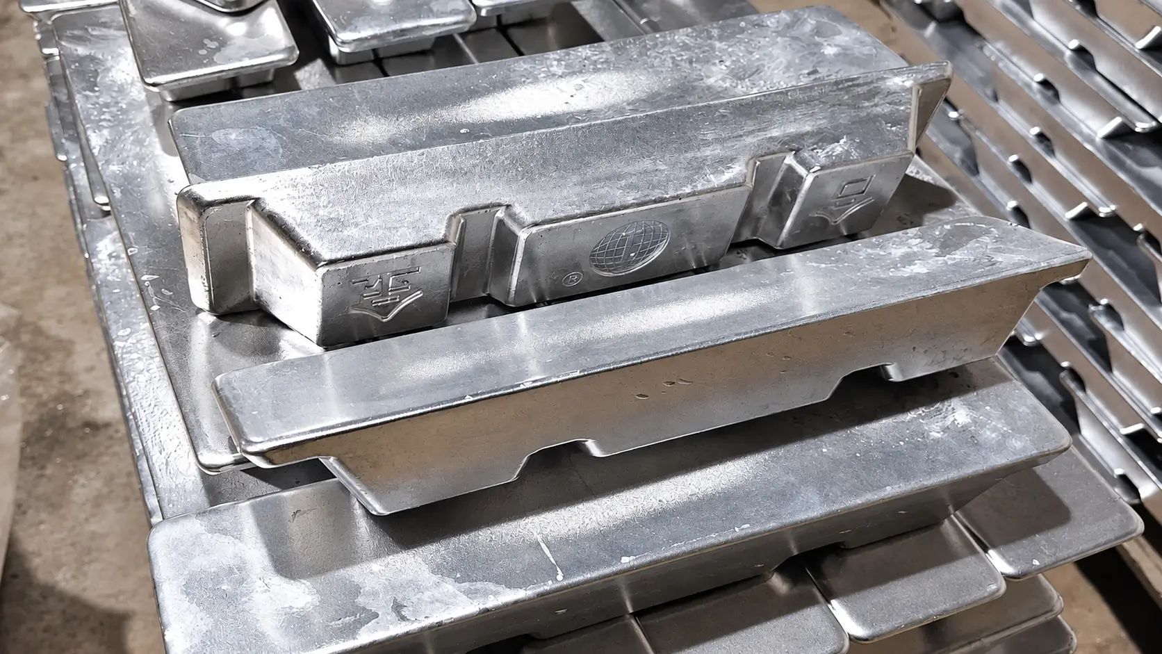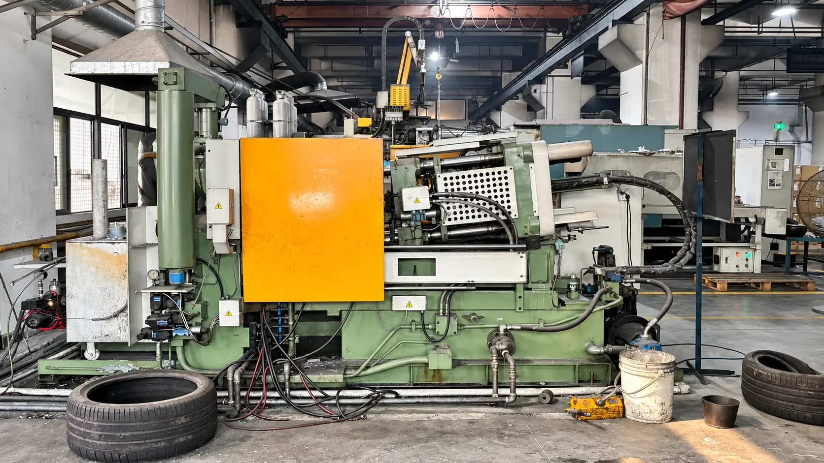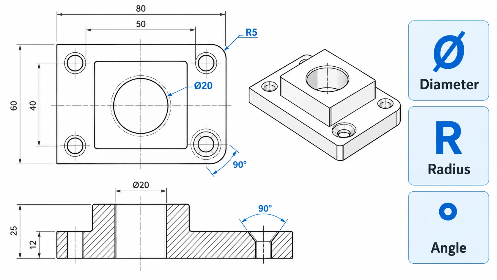

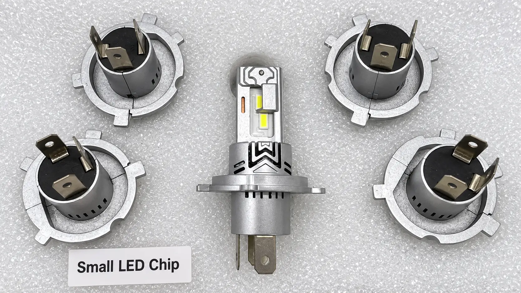
Producing these parts requires coordinated decisions about alloy selection, part design, tooling, secondary machining, and finishing. This guide explains what engineers and buyers should review at each stage, including the drawing details and inspection requirements needed to prepare a zinc component for quotation and production.
What Are Zinc Die Casting Components?
Zinc die casting components are metal parts produced by injecting molten zinc alloy into a reusable steel mold under pressure. The mold forms the main geometry, including walls, ribs, bosses, and openings. After casting, gates and flash are removed, with machining and surface finishing applied where required.
The finished component must meet its role in the assembly. A connector housing may require accurate mating features and a controlled plating thickness, while a handle may need strength, a smooth surface, and secure mounting points. These functional and appearance requirements help determine which features can remain as cast and which need additional processing.
Why Use Zinc Alloys for Die Cast Components?
Zinc alloys can reproduce fine details, thin walls, and integrated features such as ribs, bosses, and lettering. This makes them useful for compact components that would otherwise require several machining operations or separate pieces. Features can often remain as cast, while critical bores, threads, and mating surfaces receive secondary machining where necessary.
Common Zamak alloys also support efficient hot-chamber production and a range of decorative finishes. However, the material must suit the application: zinc is relatively heavy compared with aluminum and magnesium, and sustained loads, operating temperature, and corrosion exposure require consideration. The choice should balance finished-part performance with tooling investment, production quantity, and finishing requirements.
Design Guidelines for Zinc Die Casting Components
Review the following design features before tooling begins. Identify functional requirements on the drawing and discuss potential adjustments with the manufacturer during DFM review.
| Design Item | Design Recommendation | What Buyers Should Confirm |
|---|---|---|
| Wall Thickness & Ribs | Use reasonably uniform walls, gradual thickness transitions, and ribs for stiffness. Avoid heavy material buildup at rib and boss intersections. | Identify load-bearing sections and ask the manufacturer to review thin walls against alloy selection, flow distance, and part geometry. |
| Draft & Undercuts | Allow draft in the direction of mold withdrawal. Simplify side holes and recesses where their position or orientation is flexible. | Highlight features where taper would affect assembly. Confirm whether undercuts require slides and how these affect tooling cost. |
| Cosmetic Surfaces & Casting Marks | Keep gates, ejector marks, and parting lines away from critical visible surfaces and mating interfaces where practical. | Mark cosmetic faces and restricted areas. Agree on acceptable residual marks and provide appearance references when needed. |
| Tolerances & Datums | Apply tight tolerances to functional dimensions and establish clear inspection datums. Identify features requiring secondary machining. | Confirm critical fits, thread specifications, and measurement references. Review dimensions spanning mold sections or moving cores. |
| Finishing Allowances | Account for material removed during polishing and added during plating or coating. Define critical dimensions in their finished condition. | Specify finish type, coating thickness, masking areas, and assembly clearances before tooling approval. |
Practical advice: Include the mating-part drawing or assembly details when requesting a DFM review. For a connector housing, for example, identifying the mating bore, fastening threads, and electrical contact areas helps the manufacturer assess casting, machining, and plating requirements together.
Manufacturing Zinc Die Casting Components
The production route depends on how the zinc component will be used after casting. A decorative handle may require polishing and plating, while a connector housing may need machined threads and controlled mating dimensions. These requirements should determine the tooling, trimming, and secondary-operation plan before production begins.
Establish the Process Through Tooling Trials
Tooling trials provide the opportunity to evaluate filling, part release, and the condition of critical features. For thin-walled housings, review incomplete filling and distortion; for decorative parts, examine surface defects that could remain visible after finishing. Record any tooling or process adjustments and evaluate the resulting samples before approving the production setup.
Control Gate Removal and Trimmed Edges
Gate and flash removal must preserve the intended part profile. Small mounting tabs, narrow slots, and edges near mating surfaces need suitable support during trimming to prevent bending or damage. Define acceptable gate remnants and burr conditions where they affect assembly, handling, or subsequent polishing.
Machine Features That Need Additional Control
Use secondary machining where the required bore, thread, sealing face, or positional tolerance cannot be achieved reliably in the casting. Plan locating features and clamping support around the casting geometry, particularly for thin walls. If machining exposes porosity, assess it against the agreed acceptance criteria rather than treating every exposed pore as equivalent.
Materials for Zinc Die Casting Components
The strongest zinc alloy is not always the most suitable choice. A housing with tabs crimped during assembly needs ductility, while a loaded handle may place greater emphasis on strength. Start with how the component will be used, assembled, and finished, then review the alloy with the manufacturer.
Zamak 3: A Starting Point for General Components
For connector housings, covers, and general hardware, Zamak 3 is often the first grade to evaluate. Its balanced properties make it a practical baseline when comparing alternatives. Before specifying a stronger alloy, establish whether loading or wear requirements justify the change.
Zamak 5: When Strength Takes Priority
Consider Zamak 5 for handles, brackets, and mechanism components where higher strength and hardness are useful. The tradeoff is lower ductility than Zamak 3. If the part includes tabs that will be bent or crimped, review that operation before choosing the grade solely for its strength.
Zamak 7: When Fine Features Matter
Zamak 7 is worth evaluating for thin sections, intricate details, and components requiring good ductility. Its fluidity can support demanding geometry, but it does not replace a suitable gating and ejection design. Highlight narrow sections and delicate features during DFM review so material and tooling decisions are considered together.
ZA-8: For Load-Bearing and Sliding Features
ZA-8 may be considered where strength and bearing performance are priorities. For a sliding component, however, alloy selection also depends on the mating material, lubrication, operating temperature, and duty cycle. Define these conditions before treating ZA-8 as an alternative to a separate bearing or wear insert.
For composition and property comparisons, see our guide to zinc alloy properties. Confirm the selected grade on the drawing and purchase specification before tooling begins.
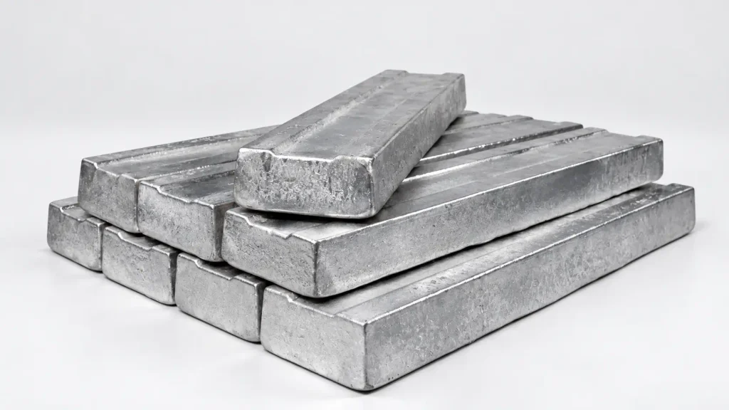
Common Applications of Zinc Die Casting Components
Zinc die casting is used for compact parts that combine detailed geometry, assembly features, and functional or decorative surfaces. The application determines which requirements need the closest control, from plated mating dimensions to mounting strength and visible surface quality.
| Component Type | Typical Parts | Key Manufacturing Requirements |
|---|---|---|
| Connectors & Electrical Hardware | Connector shells, cable fittings, and mounting bodies | Mating dimensions, thread quality, burr removal, and plating thickness |
| Locks & Security Hardware | Lock housings, latch components, and handles | Bore locations, moving-part clearances, strength, and wear requirements |
| Consumer Electronics | Device frames, covers, knobs, and decorative trim | Thin sections, assembly fit, gate marks, and cosmetic finish |
| Automotive Hardware | Interior handles, brackets, and mechanism components | Dimensional repeatability, operating conditions, and coating durability |
| Industrial Equipment | Levers, mounting brackets, and control knobs | Load-bearing sections, fastening features, and dimensional inspection |
For example, a connector shell must be evaluated at its finished, plated dimensions, while a visible handle may require agreed limits for polishing marks and surface defects. Identifying these requirements on the drawing helps align tooling, machining, finishing, and inspection before production.
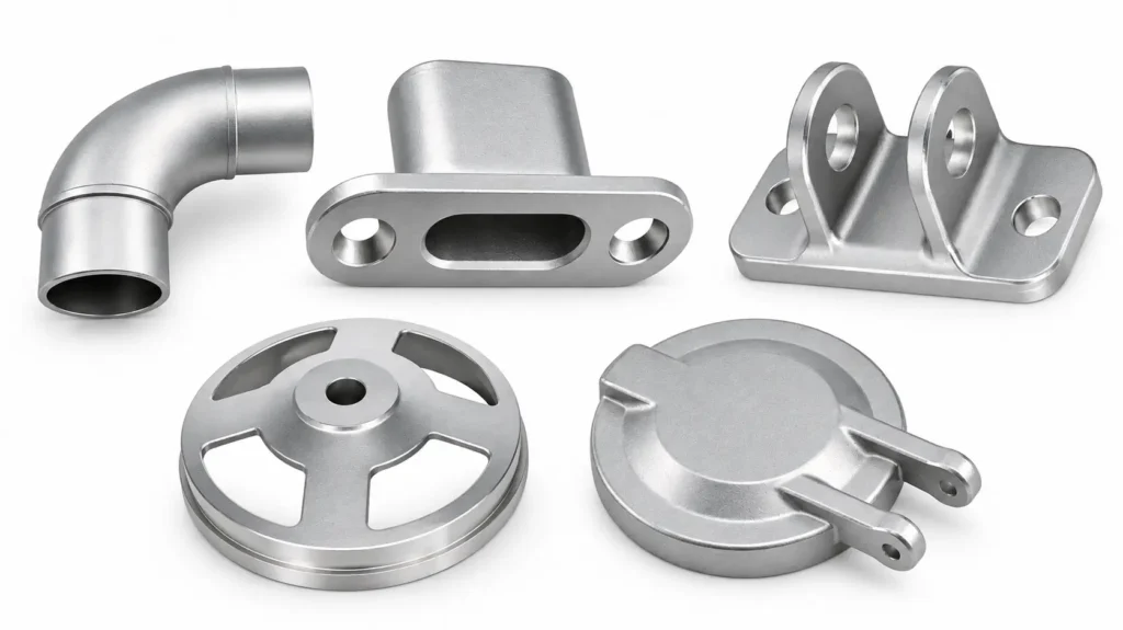
Quality Inspection for Zinc Die Casting Components
Inspection focuses on features that determine whether the finished component fits, functions, and meets appearance requirements. Critical bores, threads, and mating surfaces are checked against the drawing using suitable measuring equipment and gauges. Where plating or coating affects assembly clearances, these features are verified after finishing.
Cosmetic surfaces are assessed against agreed samples or visual criteria, including limits for gate marks, polishing marks, and coating defects. Additional checks, such as coating thickness, adhesion, corrosion testing, or assembly trials, are selected according to project requirements. Sample approval records and production inspection results provide references for subsequent batches.
What to Include in a Zinc Die Casting RFQ
A useful RFQ gives the manufacturer enough information to assess tooling, production, finishing, and inspection together. Send the 3D model and current 2D drawing, identifying the alloy, critical dimensions, datums, threads, and any features requiring machining. Clarify discrepancies between the model and drawing before the tooling scope is agreed.
Include the first-order quantity, expected annual demand, and delivery schedule so suppliers can evaluate cavity count and production planning. For plated or painted parts, specify visible surfaces, finish requirements, masking areas, and whether critical dimensions apply after finishing. Inspection reports, assembly checks, and packaging requirements should also be stated so quotations cover the same finished-part requirements.
For project-specific guidance, share your files with our zinc die casting team. We can review the part requirements and clarify tooling, secondary machining, and finishing needs before preparing a quotation.
FAQ
Yes, provided the alloy, protective finish, and part design suit the exposure conditions. Moisture, salt, contact with dissimilar metals, and areas that trap water should be considered. Any corrosion testing requirements should be agreed before production.
Sometimes. Conversion requires a review of material performance, wall sections, draft, tooling access, and production quantity. Critical features may still need machining. Compare the total cost of tooling and finished parts rather than assuming casting will always be cheaper.
Both approaches are possible, depending on thread geometry, tooling, and functional requirements. Threads may be tapped into cast pilot holes or produced through other suitable methods. Specify the thread standard, engagement depth, and inspection requirements for review.
Some zinc alloys and component geometries support secondary forming, but suitability must be evaluated. Alloy ductility, section thickness, bend geometry, and casting quality influence the risk of cracking. Validate the operation on representative samples before approving production.
The supplier should assess whether the change can be achieved by machining, replacing an insert, or more extensive tooling work. Request a review of modification costs, sample validation, and delivery impact before approving the change.