

Engineering drawing symbols communicate requirements that a part’s outline cannot show on its own. A diameter mark identifies a circular feature; a depth symbol limits how far a hole extends; a geometric tolerance controls a relationship that a size dimension alone does not describe.
Reading these marks means more than recognizing their names. You also need to identify the feature they apply to, read the accompanying values, and check the drawing’s units, notes, and referenced standards. This guide focuses on the symbols and callouts commonly found on mechanical part drawings used for CNC machining.
Common Engineering Drawing Symbols Chart
Start with the symbols used to describe dimensions and machined features. The examples below assume millimeters unless stated otherwise. They illustrate notation rather than provide complete manufacturing specifications.
| Symbol or Notation | Meaning | Example and Interpretation |
|---|---|---|
| ⌀ | Diameter | ⌀10 identifies a nominal diameter of 10. |
| R | Radius | R3 identifies a nominal radius of 3. |
| SR | Spherical radius | SR10 applies to a spherical surface with a nominal radius of 10. |
| S⌀ | Spherical diameter | S⌀20 identifies a spherical diameter of 20. |
| □ | Square feature | □12 identifies a square feature with nominal sides of 12. |
| ° | Angle in degrees | 90° identifies the specified angle. |
| ± | Bilateral dimensional tolerance | 20 ±0.1 permits a size from 19.9 to 20.1. |
| ↧ | Depth | ⌀6 ↧12 identifies a nominal 6-diameter hole with a specified depth of 12. |
| ⌴ | Counterbore | ⌴ ⌀10 ↧4 identifies a nominal 10-diameter counterbore, 4 deep. |
| ⌵ | Countersink | ⌵ ⌀12 × 90° identifies a nominal 12-diameter countersink with a 90° included angle. |
| 4X | Number of occurrences | 4X ⌀6 applies the hole-size callout to four occurrences. |
| THRU | Through feature | ⌀6 THRU specifies a hole through the indicated material thickness. |
| REF or parentheses | Reference dimension | Identifies information provided for reference, subject to the drawing’s convention. |
The rendered appearance of a symbol can vary between fonts and CAD systems. A symbol chart helps with recognition, but the original drawing remains the source for its exact application.
Dimension and Hole Symbols
Diameter and Radius
The diameter symbol, ⌀, specifies the full width of a circular feature. It can apply to a hole, shaft, bore, or another cylindrical feature. R specifies a radius, commonly used for fillets, rounded corners, and arcs.
A diameter of 10 and a radius of 10 describe very different geometry. Follow the dimension line or leader to the relevant feature before reading the number.
On a milled pocket, an internal corner marked R3 also affects tool access. A square-ended cutter still leaves a radius in the plan-view internal corner. Whether that corner can be produced depends on cutter diameter, pocket depth, access, and the required tolerance—not the radius value alone.
Depth and Through Holes
A hole diameter does not tell you whether the hole stops inside the part or passes through it.
For example, ⌀6 THRU describes a nominal 6-diameter through hole. A callout containing ⌀6 ↧12 introduces a specified depth instead. For blind holes, check the depth reference and the drawing’s applicable convention; do not assume that the full-diameter depth and the drill-point depth are identical.
This distinction matters near another cavity or a thin remaining wall. A correct diameter cannot compensate for an incorrect hole depth.
Counterbores and Countersinks
A counterbore is a cylindrical recess with a flat seating surface. A countersink is a conical recess. Their symbols may appear alongside the main hole diameter, but the recess has its own requirements.
Read a counterbore callout as a set: the main hole, recess diameter, and recess depth. Read a countersink callout for its specified diameter and included angle. Do not select the angle simply from the screw size.
These features often accommodate fastener heads. Replacing one with the other changes the seating geometry, even when the through hole remains the same.
Repeated Features and Chamfers
4X ⌀6 means that the diameter requirement applies to four occurrences. It does not define their spacing or location; those come from other dimensions and, where specified, geometric tolerances.
A chamfer may be shown as 1 × 45°. Read it with the leader and drawing convention to identify the edge and how the chamfer size is defined. A chamfer callout is a specific feature requirement; a general deburring note should not be treated as an equivalent instruction.
Thread Callouts and Common Abbreviations
Thread callouts combine several pieces of information. Consider M6 × 1–6H on an internal metric thread:
M identifies an ISO metric thread.
6 is the nominal diameter in millimeters.
1 is the pitch in millimeters.
6H identifies the internal-thread tolerance class.
The callout still needs enough context to establish whether the thread is through or blind and, for a blind thread, its required depth. Thread depth and drilling depth are separate requirements. Space may be needed beyond the usable thread for the tool and hole bottom.
An inch-series callout such as 1/4–20 UNC–2B uses a different system: nominal diameter, threads per inch, thread series, and internal-thread class. Do not interpret “20” as a metric pitch.
Older drawings and company-specific prints may also use abbreviations:
| Abbreviation | Common Meaning |
|---|---|
| DIA | Diameter |
| RAD | Radius |
| DP | Depth |
| CBORE | Counterbore |
| CSK | Countersink |
| THRU | Through |
| EQ SP | Equally spaced |
| TYP | Typical |
| REF | Reference |
Use the drawing’s legend and notes when available. In particular, a “typical” instruction must identify its intended scope clearly; it should not be extended to features merely because they look similar.
Surface Texture Symbols
Surface texture requirements describe the condition of a surface, rather than its overall size or position. The graphical symbol and accompanying specification must be read together.
Common surface-texture symbol forms distinguish between a surface for which the process is not restricted by that symbol, one requiring material removal, and one where material removal is prohibited. Additional information can identify roughness parameters, texture direction, or other requirements.
Ra is a profile roughness parameter. A specified Ra limit does not, by itself, require polishing, grinding, or a particular visual appearance. The process must be selected to achieve the requirement on the actual material and geometry.
Two surfaces with similar Ra values can have different machining marks. A sealing or sliding application may therefore need information beyond a single roughness value.
ISO 21920-1 covers the indication of profile surface texture. Legacy drawings may reference earlier standards, so avoid assigning a universal meaning to an unlabeled number without checking the applicable convention.
GD&T Symbols and Datum References
Dimensional tolerances control permitted variation in dimensions. Geometric dimensioning and tolerancing adds controls for form, orientation, location, and runout.
| Symbol | Characteristic | Basic Purpose |
|---|---|---|
| ⏤ | Straightness | Controls straightness of the specified line element or derived feature. |
| ⏥ | Flatness | Controls a surface between two parallel planes. |
| ○ | Circularity | Controls circular form in individual cross-sections. |
| ⌭ | Cylindricity | Controls the form of a cylindrical surface. |
| ∥ | Parallelism | Controls orientation parallel to a datum reference. |
| ⟂ | Perpendicularity | Controls orientation at 90° to a datum reference. |
| ∠ | Angularity | Controls orientation at a specified angle to a datum reference. |
| ⌖ | Position | Controls the location of a feature’s axis, center plane, or other applicable derived feature. |
| ⌒ | Profile of a line | Controls the specified profile in cross-section. |
| ⌓ | Profile of a surface | Controls the specified surface profile. |
| ↗ | Circular runout | Controls runout at individual sections relative to a datum axis. |
| ↗↗ | Total runout | Controls runout over the specified surface relative to a datum axis. |
Symbols are shown using text characters for reference. The paired arrows for total runout are an approximation; consult the original drawing for the formal symbol.
Text characters are useful for identification, but their appearance depends on the font. Use correctly drawn symbols in the original drawing, particularly when distinguishing circular runout from total runout.
Reading a Feature Control Frame
A feature control frame generally combines a geometric characteristic, tolerance information, and datum references where required.
For example, consider a position control containing these compartments:
Position | ⌀0.2 | A | B | C
For a cylindrical hole-axis application, this specifies a cylindrical position tolerance zone of diameter 0.2, located and oriented by the basic dimensions and referenced datum system. It is not the same instruction as a coordinate dimension of ±0.2.
The frame must also be correctly associated with the controlled feature. Its location on the drawing is part of the specification.
Datums and Material Condition Modifiers
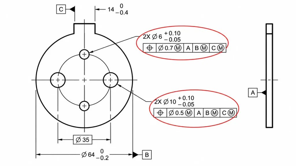
A datum feature is a physical feature identified on the part. A datum is the theoretically exact reference established from that feature. In the drawing below, A, B, and C identify datum features, and their sequence in each feature control frame establishes the priority of the references.
The two nominal ⌀6 holes have a position tolerance of ⌀0.7Ⓜ, while the two nominal ⌀10 holes have a position tolerance of ⌀0.5Ⓜ. The circled M after each tolerance value specifies maximum material condition—the smallest permitted hole size. As the hole departs from that size, additional position tolerance becomes available under the applicable rules.
The circled M after datum references B and C has a different meaning: these datum features are referenced at maximum material boundary. Clearance between the actual datum features and their boundary simulators can permit datum shift. This should not be treated as a simple addition to the stated position tolerance.
Read each frame together with the hole-size limits above it: size tolerance controls the hole diameter, while position tolerance controls its location and orientation relative to the referenced datum system. For a broader introduction, see What Is GD&T?.
Read the Drawing Standard Before Applying Defaults
ASME Y14.5 establishes dimensioning and tolerancing rules, symbols, and definitions. Within the ISO system, ISO 129-1 addresses the presentation of dimensions and associated tolerances; geometric tolerancing and surface texture are addressed by other standards. ASME
Similar-looking symbols do not make ISO and ASME specifications interchangeable. Defaults, terminology, and interpretation can differ, and the referenced edition matters.
Before using any chart, check the title block and notes for units, applicable standards, general tolerances, and revision. A reference table supports that reading; it does not override the drawing.
Reading Symbols on a Machined Part Drawing
Consider a simplified aluminum mounting plate. Its drawing specifies a thickness, four mounting holes, two threaded holes, one seating surface, and geometric controls for selected features.
Begin with the title block: confirm the drawing revision, material, and units. Next, use the views and projection indication to understand which face each feature belongs to.
Then work through the requirements:
- Four holes marked 4X ⌀6 THRU. Identify all four holes, their locations, and the applicable size tolerance. “THRU” describes their extent, not their position accuracy.
- Two holes marked M6 × 1–6H. Check their locations and the separate through/blind and depth requirements. The thread designation alone does not provide all of these details.
- A seating face identified as datum feature A. Establish which physical face is intended to provide the reference. Do not assume every broad face is a datum.
- A flatness requirement on the seating face. This controls that face’s form. Flatness itself does not require a datum reference.
- A position control on the mounting holes. Read the basic locations, tolerance zone, modifiers, and datum sequence together.
- A surface texture requirement on a mating face. Identify exactly which face it applies to and whether other surfaces have a different general requirement.
For machining, these relationships influence setup planning and support. For inspection, they determine which features must be checked and how the references are established. A checklist of hole diameters alone would miss much of the drawing’s intent.
Common Drawing Interpretation Mistakes
Reading only the number. A radius, diameter, depth, and angle can use the same numerical value while describing entirely different requirements.
Treating nominal geometry as a complete specification. A 3D model may define shape, but required tolerances, surface texture, threads, and notes still need to be identified in the supplied documentation.
Assuming every surface needs the tightest requirement. Local callouts have defined targets. General requirements must be read for their scope rather than extended or ignored by habit.
Using reference information as an independent acceptance limit. Reference dimensions help explain geometry; inspect the controlling dimensions and requirements instead of assigning a separate tolerance to reference information.
Resolving conflicts by guessing. If the model, drawing, or notes disagree, identify the conflicting feature and request clarification before production. Do not assume the model or a particular note automatically takes precedence without an applicable document rule.
From Drawing Requirements to Machined Parts
Engineering drawing symbols are useful when they can be connected to an actual feature, an allowable variation, and a practical inspection requirement. Start with the drawing context, identify the feature, and read the whole callout before deciding what it requires.
At ZH Precision, drawing review supports process planning for custom CNC machined parts. We consider material, feature access, workholding, critical dimensions, and inspection requirements together. Where a callout is incomplete or conflicting, the next step is to clarify that requirement with the customer so the machining plan reflects the intended part.



