

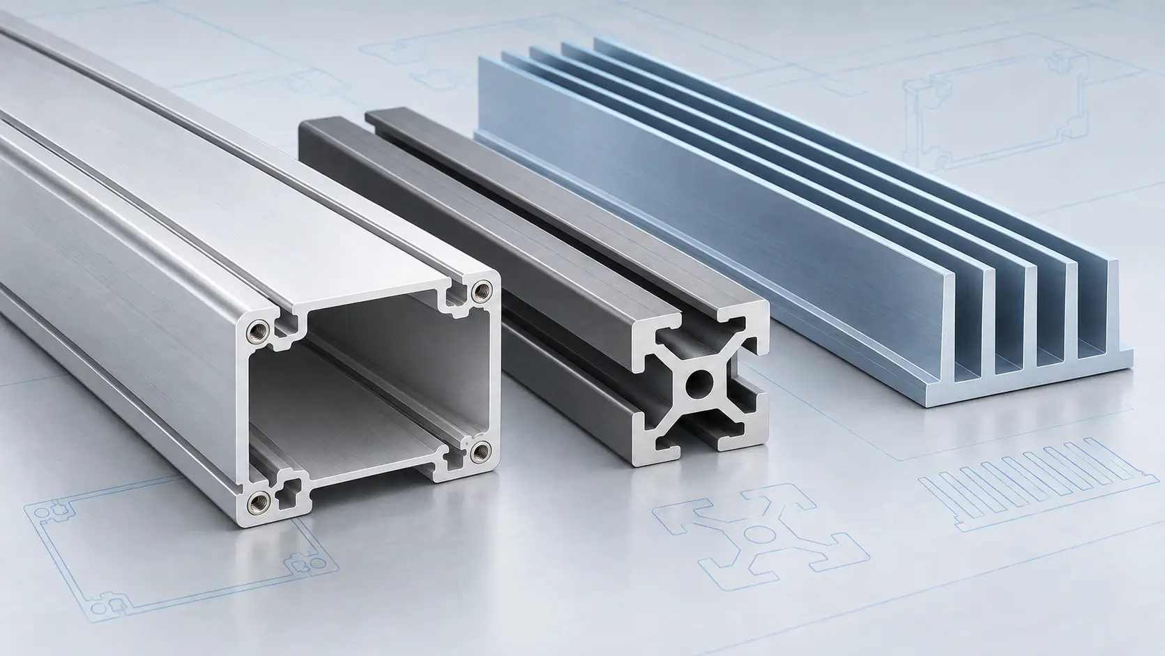
Good aluminum extrusion design resolves these details before tooling begins. This guide covers wall thickness, corners, channels, reinforcement, and connections, with design examples showing what to change and what to check afterward.
What Makes a Good Aluminum Extrusion Design?
A good aluminum extrusion design uses its cross-section to meet the product’s strength, weight, and assembly requirements. Ribs can support broad surfaces without making every wall thicker, while screw ports and retaining slots can provide connection points within the profile itself. Each feature should serve a clear purpose, whether it supports a load, holds a component, or provides a mating surface.
The drawing must also distinguish features that remain as extruded from those requiring additional processing. An enclosure’s outer walls may need only general dimensional control, while its sliding channel needs a defined clearance and its mounting face requires machining. Establishing these differences helps avoid unnecessary precision requirements across the entire section.
Aluminum Extrusion Design Guidelines
Review the profile together with its mating components. A change that simplifies extrusion is useful only if the revised section still supports the load, retains the fastener, or provides the required assembly clearance.
Keep Wall Thickness Balanced
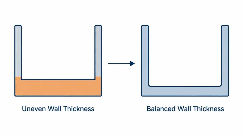
A thick enclosure base joined to thin sidewalls creates an abrupt change in section. Uneven metal flow and different cooling rates can contribute to distortion, while the extra material increases weight. Before thickening the whole base, identify whether the requirement comes from panel stiffness, screw engagement, or a mounting surface.
For panel stiffness, consider ribs positioned to support the loaded area. Retain local thickness where fasteners or mounting points need it, and blend those sections into adjacent walls. If the base will be machined, define the finished thickness separately from the extrusion allowance. The practical minimum wall depends on the alloy, profile size, unsupported spans, and tooling; it should not be selected from a universal value.
Use Radii and Smooth Thickness Transitions
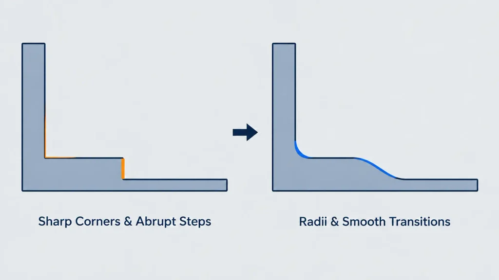
An internal radius can improve the extrusion geometry but interfere with an adjoining component. In an enclosure, a square-edged cover may contact the corner fillet before reaching its locating surfaces. The overall width can be correct while the cover still fails to seat.
Check the assembled cross-section before fixing the radius. A chamfer or clearance in the cover may preserve the extrusion’s rounded corner without additional machining. Where mating geometry cannot change, consider local machining of the affected area. At thick-to-thin junctions, use smooth, radiused transitions rather than abrupt shoulders, while preserving the space needed by nearby parts.
Design Channels and Semi-Hollow Sections Carefully
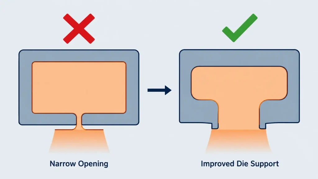
A large cavity behind a narrow opening requires a die tongue supported through that opening. Deep, narrow channels can create slender tooling features that must withstand extrusion pressure. General Extrusions’ guide illustrates several ways to improve these sections, including balancing the cavity around its opening, rounding internal corners, and reducing the enclosed area. Design-Guide
For a retaining slot, widening the opening is only useful if the fastener remains captured. Compare alternatives: reduce unused space inside the cavity, adjust the cavity position, or revise the fastener interface. If a nearly closed enclosure remains difficult, evaluate two simpler profiles joined afterward, accounting for the additional connection and assembly work.
Use Ribs and Webs Where They Provide Support
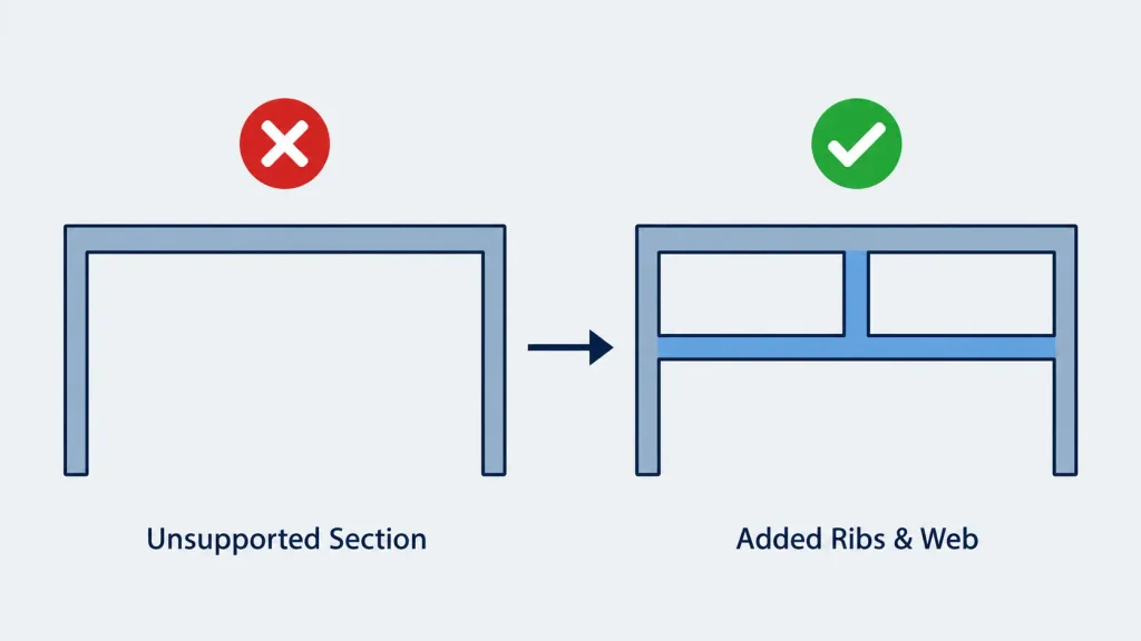
A broad, thin panel may need reinforcement, but a rib’s position matters as much as its presence. Place it where it supports the panel’s loading and leaves room for internal components. A connecting web can also help control the relationship between two walls, although it may obstruct a cable path, sliding insert, or assembly opening.
For a heat sink, review fin thickness, height, spacing, and root geometry together. Closely spaced, tall fins create demanding die features. Shortening or spreading the fins may improve manufacturability, but the revised arrangement must still meet the thermal requirement. Confirm the available airflow and mounting space rather than treating maximum fin count as the design objective.
Integrate Fastening and Assembly Features
A T-slot can fit a nut in cross-section yet prevent its installation once an end cap is attached. A screw port can provide adequate engagement while leaving insufficient space for the driver. These problems are easier to identify in an assembly sequence than in an isolated profile drawing.
Check how each fastener enters, how it is tightened, and whether it must be removed during maintenance. For sliding connections, define clearance over the engagement length and account for surface finishing. Extruded screw ports can be tapped afterward or used with suitable thread-forming fasteners. Conventional helical threads are produced in a separate operation, rather than directly by constant-section extrusion.
Define Profile Size and Critical Dimensions
The circumscribing circle is the smallest circle enclosing the complete cross-section. A projecting flange can increase this diameter even when the main body remains compact. Review whether the projection is necessary or whether its function can be achieved closer to the body.
Then identify the dimensions controlling fit. A retaining groove, sliding channel, or mounting interface may need tighter control than the surrounding walls. Specify relevant straightness and twist requirements over the working length, and locate machined holes from clear reference surfaces. For a precision mounting face, distinguish the extrusion allowance from the final machined dimension rather than applying the finished tolerance to the raw profile.
Aluminum Alloy and Temper Selection
6063 is commonly used for frames, enclosures, and profiles where extrusion complexity and appearance are important. 6061 is frequently selected for structural and machined components. The choice should follow the required properties and section geometry rather than strength alone.
Specify both alloy and temper. If the component will be formed, welded, or heat-treated after extrusion, review the properties required in its final condition. For visible anodized parts, agree on appearance requirements and use representative samples where color or finish consistency is important.
Secondary Machining and Surface Finishing
Extrusion creates features that continue along the profile’s length. Transverse holes, local pockets, end details, and precision seating surfaces can require secondary CNC machining. Provide accessible clamping areas and material for machining cleanup. A thin wall surrounding a threaded hole may need local reinforcement, but that reinforcement should be reviewed alongside the wall-balance requirements.
State whether critical dimensions apply before or after surface finishing. Coatings and anodizing can affect a close-fitting groove or sliding interface, so identify surfaces requiring masking or controlled treatment. Mark visible faces separately from ordinary surfaces, and define the required appearance instead of relying on a general finish note.
Common Aluminum Extrusion Design Mistakes
Use the table below to review common cross-section problems before tooling. Check each proposed change against the part’s strength, assembly, and finishing requirements.
| Design Problem | Potential Risk | Recommended Change | Design Trade-Off |
|---|---|---|---|
| Abrupt thick-to-thin transition | Uneven metal flow and cooling can contribute to distortion | Balance adjacent walls and blend thickness changes with radiused transitions | Retain material needed for loads and fastener engagement |
| Deep cavity with a narrow opening | Slender die tongues can deflect or fail | Reduce cavity depth, widen the opening, or improve tongue support | Preserve retention and assembly functions |
| Tight tolerances on every dimension | Unnecessary tooling, production, and inspection demands | Identify functional dimensions and machine selected features where necessary | Secondary machining adds operations and requires allowance |
| Sharp internal corners | Difficult extrusion geometry and stress concentration under load | Add suitable radii and check mating-part clearance | The mating component may need a chamfer or relief |
| Unbalanced cross-section | Uneven flow can increase distortion risk | Review material distribution and specify relevant straightness and twist requirements | Changes must preserve mounting and internal space |
| Tall, closely spaced thin fins | Demanding die geometry and vulnerability to handling damage | Review fin height, spacing, thickness, and root support | Recheck thermal performance, weight, and available space |
Conclusion
Review an aluminum extrusion as both a manufactured section and an assembled component. Balance wall thickness, support difficult channels, and check connections against the actual fasteners and mating parts. Clearly separate extrusion requirements from machining and finishing requirements so every operation works toward the same final dimensions.
FAQ
There is no universal minimum. Practical wall thickness depends on the alloy, profile size, section type, and tooling. Larger profiles and difficult hollow sections generally need thicker walls. Confirm the complete cross-section with the extruder rather than applying a minimum taken from an unrelated profile.
Not exactly. Local thickness can increase around loaded areas or fastener connections. However, large differences between adjacent walls can cause uneven extrusion and cooling, making dimensions harder to control. Keep walls reasonably balanced and use rounded transitions where thickness changes.
Extrusion tolerances vary by dimension, profile geometry, alloy, and temper. Specify critical widths, gaps, straightness, twist, and flatness against the applicable tolerance tables. Tighter requirements need agreement with the extruder; one blanket ± value does not describe every feature on a profile.
6063 is commonly selected for complex profiles, frames, heat sinks, and visible housings. 6061 is often preferred for structural components requiring higher strength. Compare the specified tempers as well as the alloys, and consider section geometry and finishing requirements before choosing.
A semi-hollow profile partially encloses a cavity through a restricted opening. Classification depends on the cavity area and opening width, not simply whether the section looks C-shaped. Narrow openings can leave slender die tongues, so cavity geometry and tooling support need careful review.
Longitudinal screw ports and screw-retaining slots can be integrated into the profile. Ports may subsequently be tapped, while suitable slots can accept specified self-tapping fasteners. Transverse holes and conventional helical threads require secondary operations. Design the connection around the chosen fastener.




