

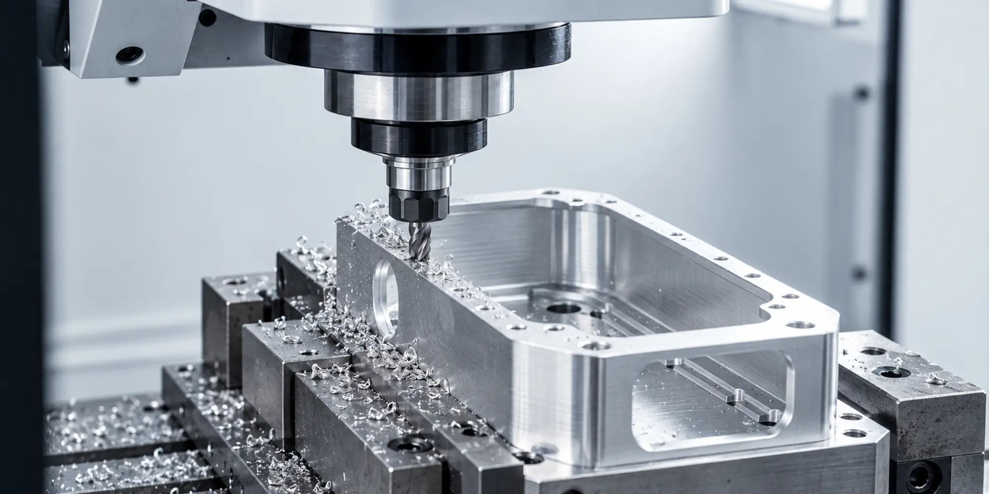
Before cutting begins, the manufacturer decides how to hold the material, which tools to use, and the order in which to machine the features. This guide follows that process from the drawing to the finished part, then explains common milling operations, applications, and the advantages and limitations of the method.
What Is CNC Milling?
CNC milling uses a rotating cutting tool to remove material and shape a part. The machine controls the movement between the tool and the workpiece, following programmed instructions. A cutter can travel across the top of a block to create a flat face, move around its edges to form a profile, or cut inside it to produce a pocket.
The workpiece is held securely while machining takes place. Depending on the machine, the table or cutting head may also rotate to give the tool access to different faces. This allows CNC milling to produce housings, brackets, plates, and other components with features in several directions.
Milling is one type of CNC machining. In conventional turning, the workpiece rotates to produce features such as shaft diameters. In milling, the cutting tool rotates, making the process well suited to flat surfaces, slots, cavities, and shaped contours.
How Does the CNC Milling Process Work?
The process begins with a drawing or CAD model. The manufacturer uses that design to plan the cutting operations, prepare the machine, and inspect the finished part.
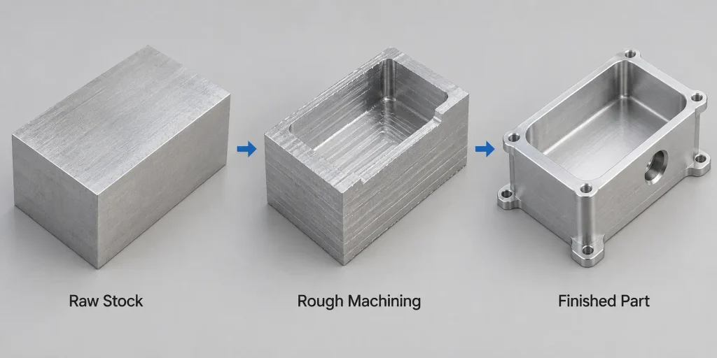
Step 1: Review the Part Design
The CAD model shows the part’s shape, while the technical drawing specifies requirements such as dimensions, tolerances, threads, and surface finish. Both are reviewed before machining.
The review also identifies features that may be difficult to cut. For example, a narrow, deep pocket can require a long, small-diameter tool, while a thin wall may bend under cutting forces. These details influence the tools and machining sequence.
Step 2: Plan the Operations and Create the Program
The programmer decides how to turn the starting material into the required shape. This includes choosing the tools, arranging the operations, and determining whether the part needs to be repositioned to reach another side.
CAM software creates the paths each tool will follow. The programmer sets cutting conditions and checks the paths for interference, then converts them into instructions suited to the CNC machine.
Step 3: Set Up the Workpiece and Tools
The operator fixes the material in a vise or fixture and installs the cutting tools. The setup must hold the workpiece securely while leaving the areas to be machined accessible.
The operator then establishes the workpiece position and tool offsets so the machine knows where each cut should occur. Program movements and clearances are checked before machining starts.
Step 4: Rough Machine the Basic Shape
Roughing removes most of the unwanted material. On a housing, this might mean opening the main cavity and cutting the outside profile, while leaving extra material on the walls and floor.
That remaining stock gives the finishing tools material to remove in controlled passes. During roughing, chips must also be cleared so they do not collect in pockets and interfere with the cutter.
Step 5: Finish the Surfaces and Features
Finishing cuts bring the part to its required dimensions and surface quality. A pocket wall may receive a separate pass, while a curved surface may need closely spaced toolpaths to reduce visible ridges.
The machining sequence can also include drilling holes, cutting threads, and adding chamfers. These operations use their own tools but can often be completed on the same machining center.
Step 6: Deburr and Inspect the Part
Cutting can leave small burrs around edges and holes. These are removed, and the part is cleaned before final inspection.
The inspector checks the features specified on the drawing, using instruments suited to each measurement. Checks may also take place during production—for example, measuring a pocket after finishing—to catch dimensional changes before more parts are made.
Common CNC Milling Operations
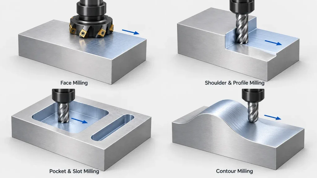
A single part often requires several milling operations. A housing, for example, may need face milling for its mounting surface, pocket milling for its interior, and profile milling around its outer edges. Each operation removes material from a different area or creates a different feature.
Face Milling
Face milling creates a flat surface, usually with a cutter that sweeps across the workpiece. It is commonly used to clean up the top of a material block or machine a mounting face.
A wide surface may require several overlapping passes. Their spacing and the condition of the cutter affect the marks left on the face. A smooth-looking surface still needs to be checked for flatness when the drawing specifies it.
Shoulder and Profile Milling
Shoulder milling creates a step where a horizontal surface meets a vertical wall. A locating ledge on a bracket is one example. The cutter removes material along the wall and the adjoining surface.
Profile milling follows the part’s outline to produce its external shape. It can form straight edges, curves, and changes in direction. Depending on the required accuracy, the outline may be roughed first and finished with a separate pass.
Pocket and Slot Milling
Pocket milling removes material inside a boundary, leaving a floor and surrounding walls. Typical examples include enclosure cavities and recesses for other components. Slot milling produces narrower channels, such as keyways and guide slots.
Deeper pockets and slots make chip removal more difficult and may require longer tools. For a blind pocket, the rotating cutter also leaves a radius where the internal walls meet. If a square mating component must fit into that corner, the design may need clearance or a corner relief.
Contour Milling
Contour milling produces shaped surfaces, such as the curved face of a mold or a rounded transition on a component. The cutter follows the surface through a series of passes, often using a ball-nose end mill.
The spacing between passes affects the ridges left behind. Closer spacing can produce a finer surface, but it also increases machining time. Some contours can be cut on a 3-axis machine; others benefit from additional rotary axes that help the tool reach angled or obstructed areas.
Drilling, boring, reaming, and tapping are also commonly performed on CNC machining centers. They create or finish holes and threads, complementing the milling operations used for the rest of the part.
CNC Milling Machine Configurations
CNC milling machines are commonly described by their spindle orientation and number of axes. These describe different aspects of the machine: vertical or horizontal identifies the spindle direction, while 3-axis, 4-axis, or 5-axis describes its available movements.
Vertical and Horizontal Milling
A vertical machining center has a vertically oriented spindle, with the cutting tool approaching the workpiece from above. This arrangement is widely used for plates, brackets, housings, and parts with pockets or features accessible from the top.
On a horizontal machining center, the spindle approaches from the side. Many machines use a rotary table and fixtures that hold parts upright, allowing several faces to be machined without manually repositioning each part. This arrangement can also help chips fall away from the cutting area, particularly when machining cavities and side features.
3-Axis, 4-Axis, and 5-Axis Milling
The number of axes affects how the tool can reach the part. More axes provide additional positioning options, but a straightforward component may still be efficiently produced on a 3-axis machine.
| Configuration | Available movement | Typical use |
| 3-axis | Linear movement along X, Y, and Z | Flat faces, pockets, slots, and holes accessible from a fixed setup |
| 4-axis | Three linear axes plus one rotary axis | Features around a part or on several sides |
| 5-axis | Three linear axes plus two rotary axes | Angled features, complex surfaces, and areas requiring different tool approach directions |
Rotary axes can reposition a part between cuts or move during cutting. In 3+2 machining, the two rotary axes orient the part and remain fixed while the three linear axes cut. Simultaneous 5-axis machining coordinates linear and rotary movements during the cut.
The practical benefit is often improved access and fewer setups. A bracket with holes on angled faces, for example, may be repositioned using rotary axes rather than removed and clamped in a different fixture. Additional axes do not automatically make every part more accurate; workholding, tooling, and process control still matter.
Advantages and Disadvantages of CNC Milling
CNC milling can produce many different features from the same piece of material. Its flexibility makes it useful for prototypes and production parts, but programming, material removal, and tool access all influence the cost and practicality of a project.
Advantages of CNC Milling
Dimensional accuracy and repeatability. Once the program and setup are established, the machine can repeat the same cutting paths across a batch. This is useful for mounting holes, locating features, and mating surfaces that need consistent dimensions. Tool wear and dimensional changes still require checks during production.
Several features in one process. A housing can have its cavity, outer profile, mounting faces, and holes machined on the same machining center. Rotary axes can provide access to additional sides, reducing the need to transfer the part between setups.
Material flexibility. CNC milling works with many metals and engineering plastics. This allows a functional prototype to use the intended production material, so testing can assess properties such as stiffness, weight, and heat resistance.
Practical design changes. A revised pocket depth or hole location can often be introduced through an updated program and setup. Dedicated molds are generally unnecessary, although custom fixtures may still be needed. This makes milling useful while a design is evolving.
Disadvantages of CNC Milling
Preparation costs. Design review, programming, tool preparation, and setup take time before the first part is cut. For a small order, those costs are shared across fewer pieces, which can increase the price per part.
Material consumption. Milling removes material as chips. A large block machined into a thin-walled housing may lose much of its original volume. Castings or extruded blanks can reduce the amount removed when their shape suits the finished component.
Tool access and geometry limits. The cutter must physically reach each surface. Deep, narrow pockets may require less rigid tools, while enclosed cavities cannot be reached directly. Conventional milling also leaves internal corner radii, which can interfere with square mating parts unless clearance is provided.
Longer cycles for demanding features. Thin walls, fine surface finishes, and tight tolerances can require lighter cuts, additional finishing passes, and more inspection. At higher quantities, casting or another process may reduce unit costs for suitable designs, even after accounting for tooling.
Materials and Applications of CNC Milling
Material choice affects both the finished part and how it is machined. An aluminum enclosure may need low weight and an anodized finish, while a steel fixture needs wear resistance and strength. The selected grade should meet those requirements before cutting tools and machining conditions are chosen.
| Material | Common CNC-Milled Parts | Machining Considerations |
| Aluminum | Housings, mounting plates, heat sinks, and brackets | Many grades machine readily; thin walls and edges need attention to deformation and burrs. |
| Stainless steel | Equipment housings, valve components, and corrosion-resistant brackets | Tool wear, heat, and work hardening require appropriate tools and cutting conditions. |
| Carbon, alloy, and tool steels | Fixtures, tooling plates, and load-bearing components | Grade and hardness affect cutting loads; heat treatment may require subsequent finishing. |
| Brass and copper | Electrical contacts, thermal components, and instrument parts | Brass often machines readily; copper can be more prone to burrs and material adhesion. |
| Titanium | Lightweight structural parts and medical components | Heat concentrated near the cutting edge makes tool condition and cutting strategy important. |
| Engineering plastics | Insulating parts, guides, spacers, and covers | Clamping pressure and cutting heat can distort the part or damage its surface. |
CNC milling is especially useful when a component needs several features located relative to one another. An electronics housing may combine an internal pocket with connector openings and mounting holes. A fixture plate needs accurately positioned holes and a flat reference face. A valve block can require passages, threaded ports, and sealing surfaces, with drilling and boring performed alongside milling.
These parts appear in automation, electronics, automotive equipment, medical devices, and other industries. The manufacturing requirements come from the individual drawing: two housings used in different industries may need similar machining, while two parts in the same assembly may require very different tools and setups.
Case Study: Medical Sensor Housing Machining
A medical equipment manufacturer needed a 6061-T6 aluminum sensor housing with internal pockets, angled fluid ports, and 1.2 mm thin walls. Selected critical dimensions required tolerances of ±0.008 mm.
The previous process used 3-axis milling and separate turning operations, requiring four manual setups. Repositioning introduced errors between features, contributing to a 14% scrap rate and a machining time of 45 minutes per part.
One Setup for Milling and Turning
We combined the operations on a 5-axis mill-turn machining center, keeping critical features referenced to one clamping setup. Controlled-engagement roughing and 70-bar through-tool coolant supported material removal and chip evacuation, while finishing allowances helped protect the thin walls.
An on-machine touch probe checked reference features before finishing. Final inspection verified the specified dimensions, with leak-tightness assessed separately where required.
Production Results
| Measure | Previous Process | Revised Process |
| Machining time per part | 45 minutes | 30 minutes |
| Clamping setups | 4 | 1 |
| Scrap rate | 14% | Below 0.2% |
| Unit manufacturing cost | Baseline | 23% lower |
Consolidating the operations cut machining time by 33% and reduced variation from repeated clamping. The main benefit was maintaining the relationship between critical features throughout machining.
Conclusion
The CNC milling process turns a design into a finished part through programming, setup, roughing, finishing, and inspection. Different milling operations create the faces, pockets, slots, and contours required by the drawing, while machine configuration determines how those features can be reached.
For a new project, identify the material, critical dimensions, and surface requirements early. Accessible features, practical internal radii, and clear tolerance callouts help simplify machining and avoid unnecessary cost.




