

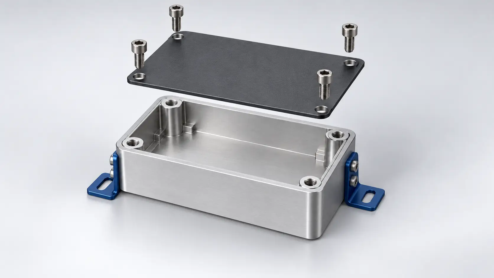
DFA works alongside design for manufacturability (DFM), which addresses how individual parts are made. For products that combine CNC machined parts, die cast components, sheet metal structures, and aluminum extrusions, both approaches help align manufacturing choices with assembly needs. This guide explains DFA principles and practical guidelines for improving how these parts fit and fasten together.
What Is Design for Assembly?
Design for assembly (DFA) is a methodology for simplifying product structures and making assembly more efficient. It aims to reduce assembly time and cost by eliminating unnecessary parts, simplifying fastening operations, and designing components that are easy to handle, orient, and insert.
DFA evaluates whether each component needs to remain separate and how it contributes to the assembly process. Combining compatible functions into one part can remove extra joints and fasteners. Clear locating features and accessible connections can also reduce the time spent aligning, holding, and securing components.
Each change must preserve the product’s functional and service requirements. Parts may need to remain separate because they move relative to one another, require different materials, or must be removed for maintenance. DFA uses these requirements to distinguish necessary components from opportunities to simplify the design.
The Difference Between DFM and DFA
Design for manufacturability (DFM) focuses on how individual parts are produced. It considers material availability, process capabilities, geometry, and tolerances. Depending on the manufacturing method, this may involve providing cutting tool access for CNC machining, adding draft to die cast features, allowing space around sheet metal bends, or designing an aluminum profile suitable for extrusion.
Design for assembly (DFA) focuses on how those parts come together. It addresses part count, handling, alignment, insertion, and fastening. Locating features, clear installation directions, and accessible fasteners help reduce assembly time and the likelihood of mistakes.
Design for manufacturing and assembly (DFMA) combines both approaches during product development. A change that simplifies assembly can also affect part production: integrating a bracket into a housing removes a separate component and its fasteners, but may increase machining or tooling costs. Evaluating both effects helps determine whether the change reduces total production cost.
| Aspect | DFM | DFA | DFMA |
|---|---|---|---|
| Focus | Making individual parts | Assembling parts | Manufacturing and assembly together |
| Design considerations | Materials, geometry, tolerances, process capabilities | Part count, handling, alignment, fastening | Tradeoffs between part production and assembly |
| Measures | Part cost, processing time, material waste | Assembly time, operations, errors | Combined manufacturing and assembly cost |
| When to apply | During part and process design | During product and assembly design | From early concept development onward |
Key Design for Assembly Principles
Assembly involves more than joining parts. Each component must be picked up, oriented, positioned, and secured, often while other parts restrict access. DFA principles help simplify these operations during design, before difficult connections or unnecessary components become part of the production process.
Reduce Part Count
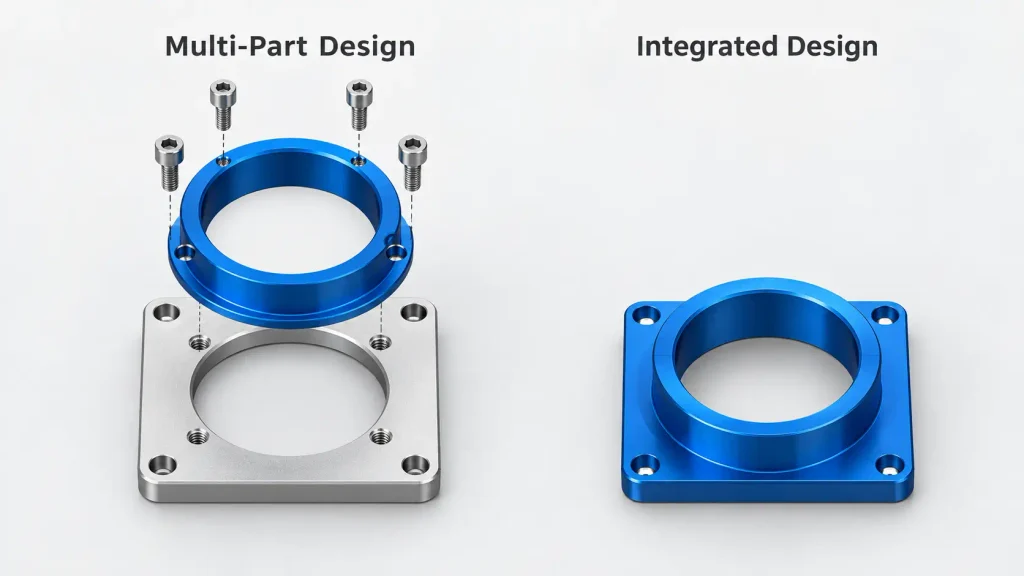
Review whether each component needs to remain separate. Parts that move relative to one another, require different materials, or provide access for maintenance may need independent construction. Where these requirements do not apply, combining functions can remove joints, fasteners, and handling operations.
A housing can incorporate mounting features that would otherwise require separate brackets. A formed sheet metal component can replace several plates joined together. However, consolidation should also account for manufacturing cost: a single complex part may require additional machining, more expensive tooling, or become costly to replace.
Standardize Parts and Fasteners
Using common screws, pins, and other components reduces the number of items that must be purchased, sorted, and selected during assembly. Consistent fastener drive types also reduce tool changes, while fewer screw lengths make incorrect selection less likely.
Standardization must still suit the connection. Thread engagement, joint loads, available space, and maintenance requirements determine which fasteners are appropriate. The aim is to reduce unnecessary variety while retaining suitable connections.
Make Parts Easy to Handle and Orient
Small, slippery, sharp, or flexible parts can be difficult to pick up and position. Provide accessible gripping surfaces where practical, remove hazardous burrs, and avoid shapes that easily tangle or nest together during storage.
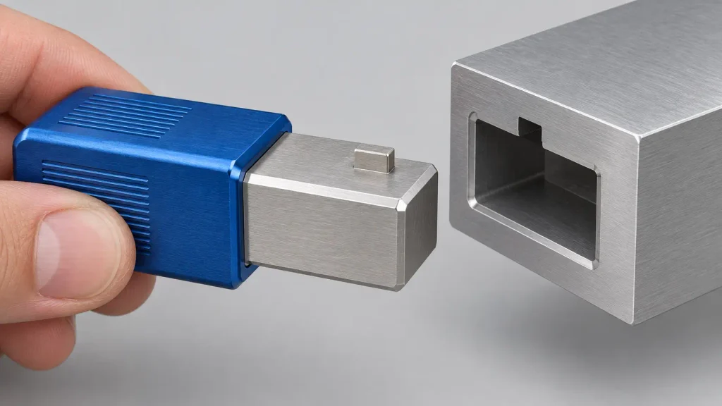
Symmetrical parts can simplify orientation when either direction is acceptable. When installation direction matters, make the difference clear. An offset hole, keyed feature, or distinct flange can help identify the correct orientation and, where designed for that purpose, physically prevent incorrect installation.
Simplify Positioning and Insertion
Parts should locate with as little manual adjustment as practical. Shoulders, locating pins, tabs, and mating recesses can establish position before fastening. This reduces the need to hold components in alignment while inserting screws.
Lead-in chamfers can guide mating features together, but they do not compensate for an unsuitable fit. Clearances must allow insertion while meeting the required alignment and movement limits. Avoid arrangements in which several tight locating features compete with one another and cause binding.
Reduce Fastening Operations and Provide Tool Access
Every separate fastener adds handling and installation work. Where joint strength and service requirements permit, integrated retention features or fewer fastening points can simplify assembly. Permanent connections should be evaluated against the need for later inspection, repair, or replacement.
Check access throughout the assembly sequence. A screw that is reachable on an isolated component may become obstructed after a cover or adjacent part is installed. Allow space for the tool, its approach direction, and the movement needed to tighten the connection.
Prevent Assembly Errors
Look for parts that can be reversed, confused with similar components, or installed in the wrong sequence. Use keyed interfaces, asymmetric mounting patterns, or distinct connection sizes to prevent incorrect combinations where practical.
Visual markings can support installation, but physical features can prevent errors even when a marking is missed. Check that those features are sufficiently distinct to block the incorrect position without making correct assembly difficult.
How to Apply DFA During Product Design
Apply DFA while the product structure and connections can still be changed. Start with the assembly model and bill of materials, then examine the operations needed to put the product together. This connects the design review to the work required during assembly and helps identify which changes deserve further evaluation.
Review the Assembly Sequence
Follow the intended installation order from the first component to the completed product. Check how each part is picked up, oriented, positioned, and secured. Pay attention to operations that require repeated alignment, product repositioning, tool changes, or holding several loose components at once.
The assembled CAD model may hide difficulties along the installation path. A component can fit in its final position yet lack enough clearance to reach it. Fasteners may also become inaccessible as neighboring parts are added. Review these intermediate steps, including removal where servicing is required.
Evaluate Opportunities to Simplify the Design
Use the review findings to identify changes that reduce assembly work. Separate spacers may be replaced by an integral shoulder, several fastener types may be standardized, or a locating feature may reduce the time spent aligning components. Assess each change against the specific operation it is intended to improve.
Before combining parts, check why they are separate. Relative movement, different material requirements, replacement needs, and access for maintenance may justify independent components. Retaining those parts while improving their connections can be more practical than consolidating them.
Check Manufacturing Feasibility and Cost
Discuss proposed changes with the manufacturing supplier before finalizing the geometry. A combined component might suit CNC machining for a small production run, while a repeated design could justify evaluating die casting. A formed sheet metal part or an extruded profile may also incorporate functions previously provided by separate pieces, depending on the required shape and performance.
Compare the revised design with the original at the intended production quantity. Include tooling, part processing, secondary machining, finishing, and assembly labor. Fewer assembly operations may justify a higher part cost, but added tooling or manufacturing complexity can outweigh the savings.
Confirm that critical interfaces can meet the required tolerances. Features produced directly by casting, bending, or extrusion may need secondary machining where accurate location or fit is necessary. Specify final dimensional requirements with the finishing process in mind.
Validate the Revised Assembly
Use prototype parts to check whether the proposed changes improve installation. Observe how easily components locate, whether mating features enter without binding, and whether tools can reach the connections. Check disassembly too if the product requires maintenance.
Record any forced alignment, manual fitting, or unexpected adjustment. Compare those observations with the drawings and measured dimensions to distinguish design problems from manufacturing deviations. Update the relevant requirements and repeat the affected checks.
If the prototype and production parts use different manufacturing processes, reassess the interfaces affected by that change. A successful trial with machined components does not establish that cast or formed versions will assemble identically.
Common Assembly Design Mistakes
DFA improvements need to be evaluated against the complete product requirements. A design may use fewer parts or assemble faster while introducing higher manufacturing costs, fit problems, or difficult repairs.
Reducing Part Count Without Comparing Total Cost
Combining components removes joints and fastening operations, but the resulting part may require more machining setups, complex tooling, or additional finishing work. Manufacturing defects can also become more expensive when several functions are concentrated in one component.
Compare the original and revised designs at the intended production volume. Include tooling, individual part costs, assembly labor, and replacement requirements. Part consolidation is worthwhile when the savings justify the added manufacturing and service costs.
Assuming Individual Part Tolerances Ensure Assembly Fit
Parts can meet their individual dimensional tolerances and still fail to assemble correctly. Variation across several components can consume the available clearance or shift mating features out of alignment. Surface treatments can further affect the finished fit.
Evaluate the dimensions and geometric relationships that control the assembled condition. Define suitable datum references, assess tolerance stack-up, and specify whether critical dimensions apply before or after finishing. Tightening an isolated dimension will not necessarily resolve a problem caused by several interacting features.
Overlooking Maintenance and Replacement
An integrated wear feature can reduce initial assembly work but require replacement of an entire housing when it wears out. Permanent connections can similarly restrict access to components that need cleaning, inspection, or repair.
Identify service items before consolidating parts or changing fastening methods. Removable covers, replaceable inserts, and accessible connections may justify additional components by reducing the work and cost of maintaining the product.
Manufacturing Parts to Meet Assembly Requirements
A part drawing defines an individual component, but the assembly model helps explain how it needs to work with neighboring parts. When requesting a quote, include the assembly model or relevant mating-part details alongside the drawings. Identify interfaces that require accurate location, sliding movement, a press fit, or sealing so the manufacturing review can focus on those requirements.
These details influence process planning. A die cast housing may need its bearing bore and mounting face machined to establish their relationship. A sheet metal cover needs its mounting holes to align after bending, while an extrusion may require machined ends and connecting holes to fit a frame. Reviewing these interfaces before production helps identify where secondary operations are needed and where drawing requirements need clarification.
Surface treatments also need to be considered at mating features. Anodizing, plating, and powder coating can change dimensions or reduce assembly clearance. The drawings should specify whether critical dimensions apply before or after finishing and identify surfaces that require masking. This allows machining allowances and finishing instructions to reflect the intended fit.
At ZH Precision, we support CNC machining, die casting, sheet metal fabrication, and aluminum extrusion projects with drawing review, process planning, and dimensional inspection. Share your part drawings, relevant assembly details, and finishing requirements so we can assess the critical features and discuss manufacturing options before production.
Conclusion
Design for assembly simplifies the work needed to handle, position, and secure components. Its principles help identify unnecessary parts, difficult connections, and opportunities to reduce adjustment during installation. Each proposed change should preserve the product’s function and maintenance needs.
Apply DFA while design changes are still practical. Review the assembly sequence, compare manufacturing and assembly costs, and validate critical interfaces through prototype assembly. Use the findings to refine drawings and inspection requirements before committing to production.




