

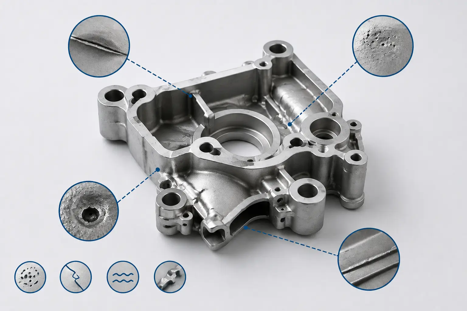
Some die casting defects are immediately visible on the surface, while others remain hidden until machining, X-ray inspection, leak testing, or assembly reveals them. A defect that looks simple may also have several contributing causes involving part geometry, gating and venting, filling conditions, cooling, or molten metal quality.
The key to troubleshooting is not simply identifying what the defect looks like. It is understanding how the defect formed and which part of the casting process is most likely responsible. For engineers sourcing parts from a die casting manufacturer, understanding these defect mechanisms also makes it easier to review tooling plans, inspection requirements, and corrective actions.
This guide covers the most common die casting defects, explains their causes, and provides practical solutions for reducing or preventing them during tooling development and production.
What Are Die Casting Defects?
Die casting defects are unwanted conditions that prevent a casting from meeting its dimensional, structural, cosmetic, sealing, or functional requirements.
They can develop while molten metal enters the shot system, during cavity filling, while the metal solidifies, during cooling, or when the casting is ejected from the die.
Surface defects such as flash, flow marks, soldering, and blisters are often easy to detect visually. Internal defects such as gas porosity, shrinkage porosity, inclusions, and laminations may remain hidden until the part is machined, sectioned, X-rayed, CT scanned, or leak tested.
Different defects can also look similar while forming through completely different mechanisms. Gas porosity and shrinkage porosity both create internal voids, for example, but the process changes needed to correct them are not the same.
Correct defect identification should therefore come before changing machine settings.
Common Die Casting Defects and Solutions
| Defect | Typical Appearance | Common Causes | Typical Solutions |
|---|---|---|---|
| Shrinkage Porosity | Irregular internal cavities | Hot spots, uneven solidification | Improve geometry, cooling, and intensification |
| Gas Porosity | Round or oval internal voids | Trapped air, poor venting | Improve filling, venting, and vacuum |
| Cold Shuts | Line or seam where flows meet | Premature cooling, poor flow pattern | Optimize temperature, gating, and fill time |
| Misruns | Incomplete or missing sections | Metal freezes before complete filling | Improve filling speed, temperature, and venting |
| Flash | Thin excess metal at die interfaces | Insufficient clamping, die wear | Check machine capacity and tooling condition |
| Flow Marks | Streaks or waves on surface | Unstable or uneven metal flow | Improve gate design and filling stability |
| Blistering | Raised surface bubbles | Subsurface trapped gas | Reduce air entrapment and lubricant gas |
| Die Soldering | Metal sticks to die surface | High local die temperature, poor release | Improve cooling and lubrication |
| Hot Tears | Irregular cracks | Restrained contraction | Improve geometry and cooling balance |
| Warpage | Bend, bow, or twist | Uneven cooling or early ejection | Improve thermal balance and ejection conditions |
| Inclusions | Foreign material inside casting | Oxides, dross, contamination | Improve melt cleanliness |
| Cuts and Washes | Raised rough areas | Localized die erosion | Optimize gate direction and metal velocity |
| Laminations | Layered internal or surface discontinuity | Overlapping or partially solidified flow | Stabilize cavity filling |
| Sink Marks | Local surface depressions | Localized solidification shrinkage | Reduce hot spots and thick sections |
| Cold Flakes | Flakes or pre-solidified metal inside casting | Premature solidification before cavity filling | Improve shot sleeve and metal transfer conditions |
Common Die Casting Defects
1. Shrinkage Porosity
Shrinkage porosity appears as irregular internal cavities, usually concentrated in thick sections or areas that solidify later than the surrounding casting. When a sample is sectioned, these cavities normally have a rougher and less rounded appearance than gas porosity.
Causes:
Molten metal contracts as it cools and changes from liquid to solid. If a region continues shrinking after its supply of liquid metal has been cut off, an internal cavity can form.
Heavy bosses, thick rib intersections, abrupt wall-thickness transitions, and other concentrated sections cool more slowly than the surrounding casting and can become localized hot spots.
In high-pressure die casting, intensification pressure can help compensate for this shrinkage while pressure is still transmitted through the gate. Once the gate has frozen, however, additional pressure has little effect on a hot spot that has already become isolated.
Solutions:
- Keep wall thickness as uniform as practical and avoid unnecessary heavy sections.
- Reduce abrupt transitions between thick and thin areas.
- Core out heavy bosses where the design allows.
- Improve local die cooling around late-solidifying regions.
- Review gate location and solidification sequence.
- Optimize intensification pressure and timing.
- Use solidification simulation to identify hot spots before the die is finalized.
Increasing pressure alone is not a reliable solution if the geometry or solidification sequence is creating an isolated hot spot.
2. Gas Porosity
Gas porosity appears as relatively smooth, round or oval voids inside the casting. It may be distributed through the part or concentrated in regions where air becomes trapped during cavity filling.
Causes:
Air can become trapped both before and during cavity filling.
In cold-chamber die casting, unstable metal movement through the shot sleeve can roll air into the molten metal before it reaches the gate. During fast cavity filling, excessive turbulence, inadequate venting, blocked vents, or poor vacuum performance can trap additional air inside the die.
Excessive die lubricant, incomplete lubricant evaporation, moisture, and inconsistent melt handling can also contribute gas.
Solutions:
- Maintain stable metal movement through the shot sleeve.
- Avoid excessive turbulence before the metal reaches the gate.
- Improve vent and overflow design.
- Keep vents clean during production.
- Optimize fast filling conditions.
- Control die lubricant quantity and spray distribution.
- Allow moisture from die spray to evaporate before injection.
- Check vacuum performance where vacuum-assisted die casting is used.
For pressure-tight or structurally important parts, X-ray or CT inspection may be required to determine the location and severity of internal porosity.
3. Cold Shuts
Cold shuts appear as lines or seams where separate molten metal flow fronts meet but fail to fuse completely.
They are commonly found around cores, holes, ribs, or other geometry that forces the incoming metal to split and later reconnect.
Causes:
A cold shut develops when one or both flow fronts lose too much heat before they meet.
Low metal temperature, low die temperature, long flow paths, excessive fill time, poor gate location, or very thin sections can all cause the leading metal to begin solidifying too early.
Aluminum alloys add another complication because oxide films form rapidly on exposed molten surfaces. Two flow fronts can therefore appear joined from the outside while a weak interface remains beneath the surface.
Solutions:
- Maintain metal and die temperatures within the established process range.
- Review cavity fill time for the part geometry and wall thickness.
- Optimize gate size and location.
- Adjust filling velocity without creating excessive turbulence.
- Shorten unnecessarily long flow paths where possible.
- Improve venting at the last regions to fill.
- Use flow simulation to identify where separate flow fronts meet.
The goal is to keep the metal sufficiently fluid when the flow fronts reconnect, not simply to increase temperature or injection speed without understanding the filling pattern.
4. Misruns and Short Fills
A misrun occurs when molten metal does not completely fill the cavity.
The result may be a missing corner, incomplete rib, partially formed edge, or another feature that does not reach its intended geometry.
Causes:
The metal may begin solidifying before reaching the final region of the cavity.
Low metal temperature, low die temperature, insufficient filling velocity, inadequate gate area, excessive flow length, or very thin walls can all contribute.
Poor venting can create a similar result. If trapped air cannot escape from the final filling area, it creates resistance against the incoming metal and can prevent the cavity from filling completely.
Solutions:
- Confirm that metal and die temperatures are within the required process window.
- Review cavity fill time.
- Optimize fast filling conditions.
- Check gate size and gate location.
- Improve venting and overflow locations.
- Inspect vents for blockage.
- Review very long or thin flow paths in the part design.
A cold shut means the metal reached the area but did not fuse correctly. A misrun means the metal did not completely reach or fill the area.
5. Flash
Flash is a thin layer of unwanted metal that escapes between die surfaces and solidifies outside the intended casting geometry.
It commonly appears along the parting line, around slides, inserts, cores, or other tooling interfaces.
Causes:
During injection, cavity pressure pushes against the projected area of the casting and creates a force that tries to separate the die halves.
If the available clamping force is insufficient, the die can open slightly and allow molten metal to escape.
Flash can also occur when the machine has adequate nominal tonnage. Worn parting surfaces, damaged shutoffs, die misalignment, contamination, or worn slides and inserts can prevent the die from closing correctly.
Solutions:
- Confirm that machine clamping force is suitable for the casting.
- Inspect parting surfaces and shutoffs for wear.
- Remove contamination that prevents complete die closure.
- Check die alignment.
- Inspect slides, inserts, and moving die features.
- Review cavity and intensification pressure if excessive force is being generated.
- Repair worn tooling before flash increases further.
Flash that gradually becomes worse during repeated production often indicates die wear or tooling condition rather than a single incorrect machine setting.
6. Flow Marks
Flow marks appear as streaks, waves, bands, or visible changes in surface texture that follow the path of molten metal through the cavity.
Causes:
Flow marks form when different areas of the cavity fill or cool under different conditions.
Poor gate placement, unstable filling velocity, low die surface temperature, long fill time, or an uneven filling pattern can cause the flow front to slow, change direction, or partially cool before filling is complete.
They are often primarily cosmetic, but they become more important on parts that require painting, polishing, plating, or another appearance-sensitive finish.
Solutions:
- Optimize gate location for a more stable filling pattern.
- Adjust filling velocity to avoid unnecessary hesitation.
- Maintain consistent die surface temperature.
- Review fill time.
- Check die spray and cooling conditions.
- Use flow simulation when marks repeatedly appear in the same region.
7. Blistering
Blistering appears as raised bubbles or bulges on the casting surface.
Some blisters are visible immediately after casting, while others appear only after the part is exposed to heat during painting, powder coating, baking, or another secondary process.
Causes:
Blisters normally form when gas is trapped just below the casting surface.
When the casting is reheated, the trapped gas expands and pushes against the thin layer of metal above it.
Turbulent cavity filling, inadequate venting, excessive die lubricant, incomplete lubricant evaporation, or poor vacuum performance can all contribute.
Solutions:
- Reduce air entrapment during cavity filling.
- Improve vent and overflow design.
- Optimize filling conditions to reduce turbulence.
- Control die lubricant quantity.
- Allow die spray moisture to evaporate before injection.
- Check vacuum performance where applicable.
Increasing cooling time after casting does not remove a gas pocket that has already formed. The gas needs to be prevented from entering or becoming trapped during the casting process.
8. Die Soldering
Die soldering occurs when casting metal adheres to the die surface and is difficult to release cleanly during ejection.
The casting may show rough, torn, or dragged areas, while metal gradually builds up on the corresponding die surface.
Causes:
Soldering is particularly common in aluminum die casting.
High local die temperature, insufficient cooling, poor release-agent coverage, direct metal impact from the gate, high local metal velocity, damaged die surfaces, and alloy chemistry can all increase the tendency for aluminum to adhere to the tooling.
The problem is often localized. A small region close to the gate may operate much hotter than the average die temperature suggests.
Solutions:
- Control local die temperature in high-risk regions.
- Improve local cooling.
- Maintain consistent release-agent coverage.
- Review gate direction and local metal velocity.
- Avoid direct high-energy metal impact on vulnerable die surfaces.
- Repair or polish damaged tooling before buildup becomes severe.
- Confirm that the selected alloy is suitable for the casting process.
9. Hot Tears and Cracks
Hot tears are irregular cracks that form while the casting is cooling and contracting.
They commonly appear near sharp corners, abrupt section changes, rigid cores, or other regions where the casting cannot contract freely.
Causes:
As the casting solidifies, different regions cool and contract at different rates.
If part geometry or tooling prevents a section from contracting freely while the metal is still relatively weak, stress can build until the material tears.
Sharp internal corners, thick-to-thin transitions, isolated hot spots, restrictive cores, and uneven cooling can all increase the risk.
Cracks may also occur after solidification because of difficult ejection or excessive mechanical force, so the actual stage at which the crack forms should be considered during diagnosis.
Solutions:
- Add appropriate radii to sharp internal corners.
- Reduce abrupt changes in wall thickness.
- Improve cooling balance around the affected region.
- Add relief where cores restrict contraction.
- Review ejector location and ejection force.
- Check for soldering or sticking that makes release more difficult.
- Consider alloy selection where geometry cannot be changed.
10. Warpage
Warpage is dimensional distortion that causes a casting to bend, bow, twist, or move away from its intended geometry.
Small amounts of distortion may not be obvious visually but can still create problems with flatness, sealing surfaces, hole position, or assembly fit.
Causes:
Warpage usually develops when different regions of the casting cool and contract at different rates.
Uneven wall thickness, asymmetric geometry, imbalanced die cooling, premature ejection, or thin unsupported sections can all contribute.
Temperature differences between the two die halves, cores, inserts, and locally cooled regions can also affect the final shape.
Solutions:
- Improve cooling balance across the die.
- Maintain stable cycle time and die spray conditions.
- Avoid premature ejection.
- Review ejector layout and release forces.
- Add ribs or structural support where appropriate.
- Use CMM or dedicated fixtures to monitor repeatable distortion.
Tooling compensation may be appropriate when distortion is stable and predictable, but it should not be used to compensate for an unstable casting process.
11. Inclusions
Inclusions are foreign solid materials trapped inside the casting.
They may include oxide films, dross, contaminated return material, refractory particles, or other contamination introduced during melting, holding, transfer, or injection.
Causes:
Molten aluminum readily forms oxides when exposed to air.
Poor dross handling, excessive melt disturbance, contaminated charge material, dirty transfer tools, or poorly controlled return material can fold these oxides or other foreign material back into the melt.
Inclusions may remain hidden until machining exposes them or the casting is sectioned during inspection.
Solutions:
- Use clean and controlled charge material.
- Maintain good furnace and holding practices.
- Remove dross without mixing it back into the melt.
- Avoid unnecessary agitation of molten metal.
- Keep transfer equipment and ladles clean.
- Control return material.
- Use filtration where appropriate for the alloy and casting process.
Chemical composition testing can verify that the alloy is correct, but it does not directly measure oxide films, dross, or overall melt cleanliness.
12. Cuts and Washes
Cuts and washes are casting surface defects caused by localized erosion of the die.
The damaged die surface is reproduced on later castings as raised, rough, or irregular features.
Causes:
High-velocity molten metal repeatedly striking the same cavity wall, core, or insert can gradually erode the tooling.
Poor gate angle, excessive local metal velocity, direct impingement, or long-term tooling wear can accelerate the problem.
This is why gate velocity and flow direction matter, not just the overall injection speed of the machine.
Solutions:
- Redirect gates away from vulnerable die surfaces.
- Change gate angle where direct impingement occurs.
- Optimize gate size and local metal velocity.
- Adjust filling conditions without creating cold shuts or misruns.
- Use appropriate die steel and surface treatments in high-wear regions.
- Inspect and repair erosion during scheduled die maintenance.
Simply reducing injection speed can solve one problem while creating incomplete filling elsewhere, so the complete flow pattern needs to be considered.
13. Laminations
Laminations are layered or overlapping discontinuities where separate portions of metal lie against one another without forming a fully sound bond.
They may appear at the surface or become visible only after machining removes the outer casting skin.
Causes:
Laminations usually develop when the filling pattern becomes unstable.
Metal may splash against a cooler die surface, begin to solidify, and then be covered by a later flow front. Oxide films between the layers can prevent complete bonding.
Poor filling control, excessive turbulence, long fill time, low die temperature, or a flow pattern that causes molten metal to overlap itself can all contribute.
Solutions:
- Stabilize cavity filling.
- Review fill time.
- Reduce unnecessary splashing and recirculation.
- Optimize gate location and metal flow direction.
- Maintain suitable metal and die temperatures.
- Use flow simulation to identify overlapping or reversing flow fronts.
Laminations can extend below the visible surface, which is why machining may expose a defect that was not obvious on the as-cast part.
14. Sink Marks
Sink marks appear as localized depressions on the casting surface, usually above a thick section or concentrated mass of metal.
Causes:
A sink mark is closely related to solidification shrinkage.
If a thick internal section continues to contract after the outer casting skin has solidified, the surface may be pulled inward instead of leaving a completely enclosed internal void.
Heavy bosses, thick rib intersections, and abrupt changes in wall thickness are common locations.
Solutions:
- Reduce unnecessary material concentration.
- Core out heavy sections where possible.
- Improve transitions between thick and thin walls.
- Improve local cooling.
- Review gate location and solidification sequence.
- Optimize intensification while pressure can still reach the affected region.
Sink marks and shrinkage porosity are related defects. The main difference is that a sink affects the external surface, while shrinkage porosity forms an internal cavity.
15. Cold Flakes
Cold flakes are pieces of metal that begin solidifying before normal cavity filling is complete and are then carried into the casting with the remaining molten metal.
They may remain embedded inside the casting and become visible only after sectioning or machining.
Causes:
Metal can begin to solidify when it contacts cooler surfaces during ladling, transfer, or movement through the shot sleeve.
If partially solidified metal remains in the shot sleeve, subsequent plunger movement can break it loose and carry it into the cavity.
Low metal temperature, an excessively cool shot sleeve, delays before injection, or inconsistent shot conditions can increase the risk.
Solutions:
- Maintain stable molten metal temperature.
- Keep metal transfer time consistent.
- Avoid unnecessary delays between ladling and injection.
- Maintain appropriate shot sleeve thermal conditions.
- Keep the initial shot movement stable.
- Maintain consistent cycle timing.
- Investigate shot sleeve condition when cold flakes repeatedly occur.
Cold flakes may create local discontinuities inside the casting and can become more significant in mechanically demanding components.
Frequently Confused Die Casting Defects
Some die casting defects can look similar on the surface or produce similar inspection results even though their underlying mechanisms are different. Visual appearance is useful for an initial assessment, but defect location, internal shape, and the corresponding tooling or process condition often provide more reliable clues.
Gas porosity and shrinkage porosity are a common example. Gas porosity normally appears as relatively smooth, round or oval voids and is associated more closely with trapped air, cavity filling, venting, vacuum performance, or lubricant. Shrinkage porosity is usually more irregular and tends to develop around thick sections or hot spots that solidify later. When the difference is not obvious, sectioning, X-ray inspection, or CT scanning can help determine the shape and distribution of the voids before process changes are made.
Cold shuts and misruns are both related to cavity filling but occur in different ways. A cold shut forms when separate metal flow fronts reach the same area but fail to fuse properly, often leaving a visible seam or weak interface. A misrun occurs when molten metal does not completely reach or fill part of the cavity, leaving missing or incompletely formed geometry. The distinction matters because improving metal flow to an unfilled region is not necessarily the same as improving fusion between two existing flow fronts.
Shrinkage porosity and sink marks share the same basic solidification mechanism. When localized shrinkage remains below a stable outer surface, an internal cavity can form. If the outer skin is pulled inward as the underlying metal contracts, the same local shrinkage may appear as a sink mark. The position of the defect relative to heavy bosses, thick walls, or rib intersections is often an important diagnostic clue.
Soldering and die erosion can both create rough or damaged casting surfaces in the same location over repeated production cycles. With soldering, casting alloy adheres to the tooling and gradually builds up on the die surface. Die erosion produces the opposite condition, with repeated high-velocity metal impact wearing away the tool surface. Inspecting the corresponding die area usually makes the distinction clearer.
Laminations and cold shuts can also be difficult to separate. A cold shut normally forms where two primary flow fronts meet without complete fusion. Laminations are more often associated with overlapping, oxidized, splashed, or partially solidified metal being covered by a later flow. A lamination can therefore remain hidden below the casting skin and only become visible after machining.
The important point is that defect names should not be assigned from appearance alone when the corrective action depends on the actual formation mechanism. Inspection results, defect location, tooling condition, and process history should be considered together before significant changes are made.
How Manufacturers Prevent Die Casting Defects
Preventing die casting defects begins before the first production shot. Part geometry should be reviewed for heavy sections, abrupt wall transitions, sharp internal corners, long flow paths, restrictive cores, and other features that may create filling or solidification problems. Gate, runner, overflow, vent, and cooling layouts should then be developed around how the actual casting geometry will fill and cool.
Before the process is released for production, die trials are used to confirm filling behavior, surface condition, dimensional stability, and internal soundness. Flow simulation can help identify trapped-air locations, unstable flow fronts, excessive local metal velocity, and difficult-to-fill areas, while solidification analysis can reveal hot spots and late-solidifying regions that may develop shrinkage porosity or sink marks. These tools are most useful when they guide tooling and process decisions before defects become repetitive production problems.
Once an acceptable process has been established, consistency becomes more important than continuously changing individual settings. Metal temperature, die temperature, fill time, injection conditions, intensification pressure, cycle time, die spray, and cooling should remain within a controlled process window. When a defect begins to appear, current conditions should be compared with previous stable production rather than changing several parameters at the same time.
Tool condition also changes throughout the production life of the die. Vents can become restricted, parting surfaces wear, gates erode, inserts become damaged, slides lose accuracy, ejector systems change, and cooling channels lose efficiency. These changes can introduce flash, porosity, soldering, warpage, and other defects even when the machine settings have not changed. Preventive maintenance should therefore be linked to both tooling condition and recurring defect patterns.
Inspection closes the feedback loop. Visual inspection is suitable for many surface defects, while CMM inspection can identify warpage and dimensional variation. X-ray and CT scanning can reveal internal porosity and other discontinuities, and sectioning can help distinguish gas porosity, shrinkage porosity, inclusions, laminations, and cold flakes. Pressure-tight castings may also require leak or pressure testing when an internal defect could create a functional leakage path.
The objective is not to eliminate every possible casting variation by adding more inspection. It is to establish a stable process, identify the defects that matter to the function of the part, and use the appropriate inspection method to verify that those risks remain controlled throughout production.
For new custom die casting projects, ZH Precision supports DFM review, tooling development, die casting production, secondary CNC machining, surface finishing, and inspection. Reviewing part geometry, tooling risks, critical dimensions, cosmetic requirements, and inspection needs before tooling begins can help reduce avoidable changes during die trials and later production.
Explore our die casting services for tooling, production, secondary machining, surface finishing, and inspection support.
Conclusion
Die casting defects rarely come from one isolated cause. Part geometry, gating and venting, filling conditions, temperature control, molten metal quality, cooling, and tooling condition can all influence the finished casting.
The first step in troubleshooting is therefore to identify the defect correctly. Gas porosity should not be treated like shrinkage porosity. Cold shuts and misruns are both filling-related defects but form in different ways. Sink marks and shrinkage porosity share the same basic solidification mechanism but appear differently. Flash, soldering, flow marks, and die erosion may all affect the casting surface, yet each points toward a different part of the process.
Once the defect has been identified, the relevant part geometry, tooling condition, process parameters, and inspection results can be reviewed systematically instead of changing several machine settings at random.
For new tooling, many defect risks can be reduced earlier through DFM review, appropriate gating and venting, filling and solidification analysis, stable process development, preventive tooling maintenance, and an inspection plan matched to the functional requirements of the casting.




