

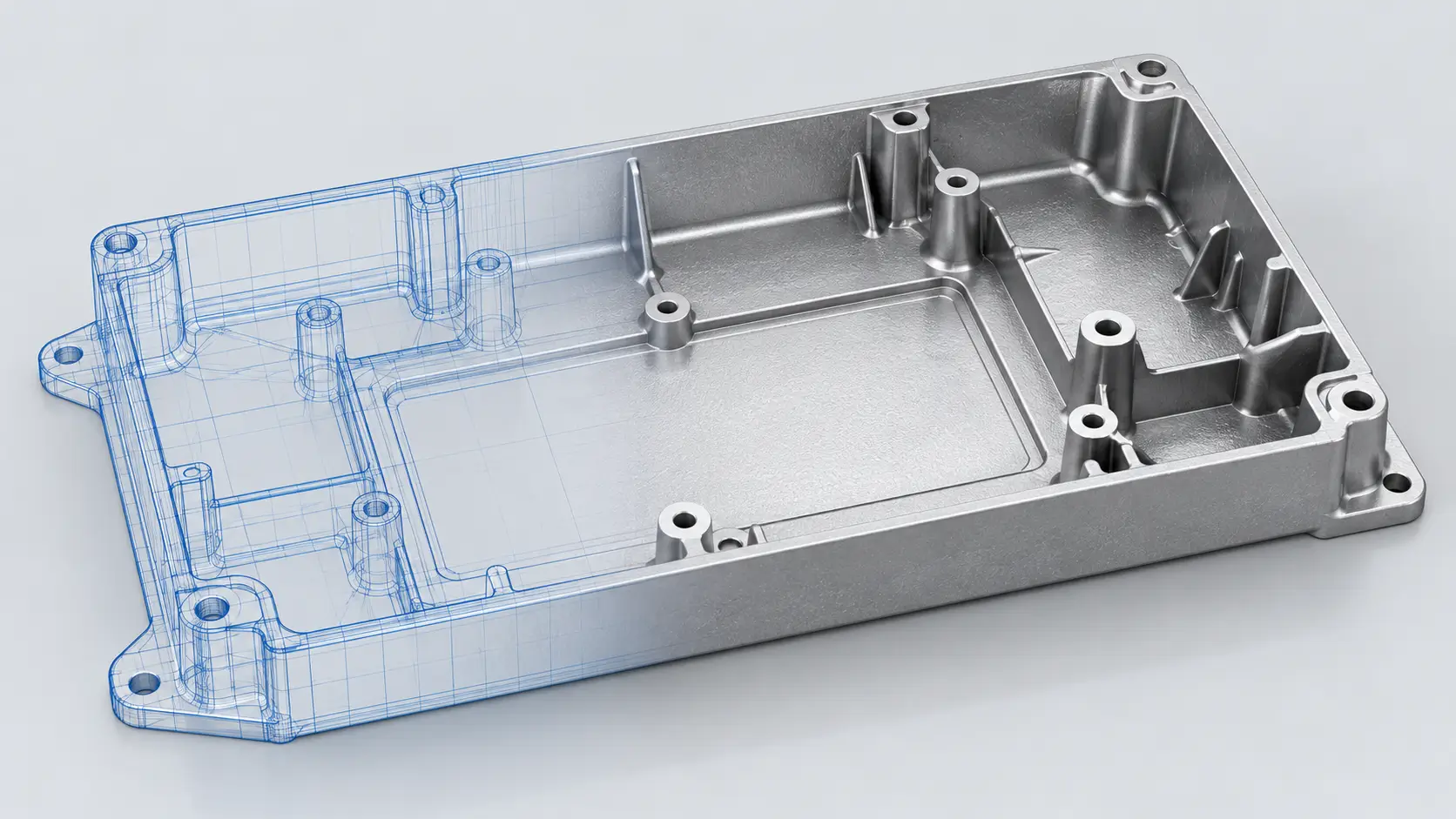
A housing may look complete in CAD but still need changes before tooling begins. Thick bosses can create local hot spots, side holes may require slides, and precision mounting faces may need CNC machining. This guide explains the main design principles and how they apply to manufacturing aluminum, zinc, and magnesium die cast parts.
What Is Die Casting Design?
Die casting design is the development of a part’s geometry and specifications for production in a reusable metal die. For conventional high-pressure die casting, molten alloy enters the cavity under pressure and solidifies before the die opens and the casting is ejected.
A suitable design must satisfy both the part’s function and the manufacturing process. Its walls must fill, its features must release from the tooling, and its critical dimensions must remain achievable through casting or planned secondary operations.
Part design and die design are closely connected. The part defines the required geometry, while the tooling provides the cavities, cores, slides, gates, cooling passages, and ejection system needed to produce it. Early collaboration with the manufacturer helps identify changes before they become expensive tooling revisions.
Why Is Design Important in Die Casting?
Design decisions influence manufacturing cost throughout the project. An undercut may add a slide mechanism; a thick section may extend cooling time; and an unnecessarily tight tolerance may require machining and additional inspection.
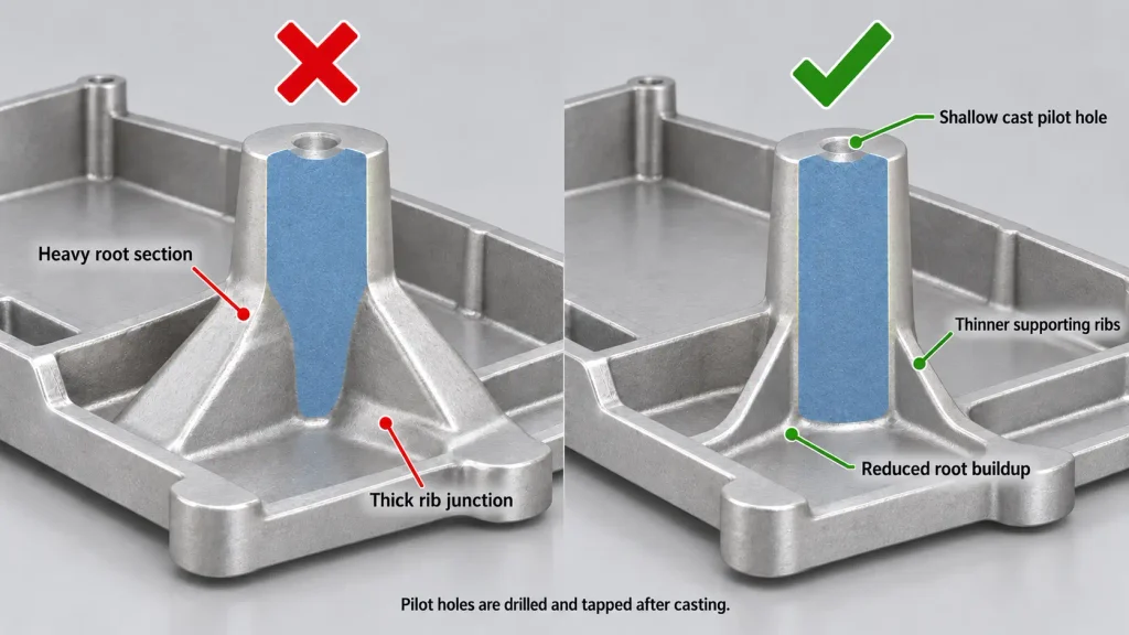
Consider an aluminum housing with four mounting bosses. Making the bosses solid adds material, but it also creates thick regions where the bosses meet the housing wall. These regions can solidify differently from the surrounding sections. Coring the bosses and supporting them with ribs may provide a more suitable geometry while maintaining the required mounting function.
Design also determines how much work remains after casting. A part that incorporates suitable cast features can reduce machining, but mating surfaces, threads, and precision bores may still require secondary operations. Planning those operations before mold construction helps provide access, support, and sufficient stock where needed.
Key Die Casting Design Principles
The following principles provide a starting point for part development. Final dimensions depend on the alloy, casting process, part size, flow length, tooling arrangement, and functional requirements. Numerical guidelines should therefore be applied within their stated conditions.
Wall Thickness and Transitions
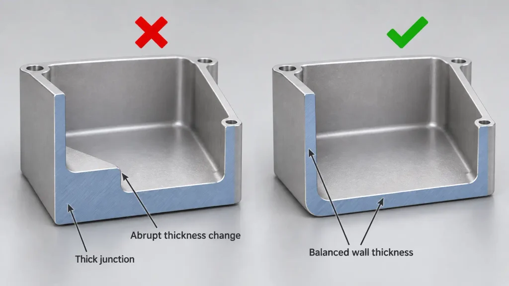
Consistent wall thickness supports more predictable filling and solidification. Abrupt changes between thin and thick sections can create local hot spots and increase the risk of shrinkage-related defects.
For a housing, the surrounding wall, mounting bosses, and rib intersections should be reviewed together. Several individually reasonable features can combine into an excessively thick junction. Coring a boss, moving a rib, or changing the intersection may reduce this material concentration.
Thin walls can reduce weight and material consumption, but they also make filling more demanding. A short wall near the gate behaves differently from a long, thin section at the end of the flow path. There is no single minimum wall thickness suitable for every die cast part.
Where thickness changes are necessary, gradual transitions are generally preferable to abrupt steps. The transition must still preserve any required mounting surface, seal interface, or machining allowance.
Draft Angles and Release Direction
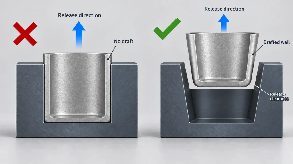
Draft is the taper provided on surfaces that must separate from the die or withdraw from a core. It helps the casting release and reduces the risk of dragging or damaging the surface during ejection.
The required draft depends on factors such as feature depth, alloy, surface texture, and tooling conditions. Internal walls may need different treatment from external walls, particularly where the casting contracts around a core.
In a deep enclosure, draft changes the opening size along the cavity depth. This matters when the housing must accept another component. The design should identify where a fit is required and whether that region can remain as-cast or needs machining.
A functional requirement for a straight bore or close-fitting face should be discussed before tooling begins. Providing machining stock may be more practical than imposing minimal draft on a feature that is difficult to release.
Ribs and Mounting Bosses
Ribs can increase stiffness without making the entire wall thicker. Their effectiveness depends on their location and connection to the surrounding structure, not simply on adding more ribs.
A mounting boss can be connected to nearby walls with ribs to distribute loads. However, oversized ribs and crowded intersections can create thick sections that undermine the intended weight reduction.
Boss design should also consider the fastener and subsequent operations. A hole intended for tapping needs sufficient surrounding material, suitable access, and a geometry that supports the required thread depth. If the boss will be drilled after casting, its position and available machining stock must accommodate casting variation.
For an enclosure, these details should be reviewed with the mounting arrangement. A rib that improves stiffness may also block a drill, interfere with a mating component, or obstruct a machining fixture.
Fillets and Corner Radii
Fillets provide smoother transitions between walls, ribs, and bosses. They can reduce sharp geometric changes and improve the structural behavior of the part.
Internal and external radii should be considered together to avoid unnecessarily thick corners. Adding a large internal fillet while leaving the outside corner unchanged can create a local material concentration.
Corner geometry also affects tooling and later machining. If an internal pocket will be CNC machined, its finished radius must accommodate the cutting tool. A sharp corner shown in CAD may need a design change or a separate manufacturing approach.
The drawing should distinguish functional radii from general edge treatment. A radius used for component clearance requires different attention from an unspecified corner break.
Parting Lines, Slides, and Undercuts
The parting line is where sections of the die meet. Its location affects tooling arrangement, flash, trimming, and the relationship between features formed by different die components.
An undercut prevents a feature from releasing along the main opening direction. Side holes, recessed side features, and some retaining details may require slides or other movable tooling.
These mechanisms can be appropriate, but they add complexity and maintenance requirements. Moving a side feature, changing its orientation, or machining it after casting may offer an alternative. The decision depends on production volume, feature requirements, and total manufacturing cost.
For a housing with a sealing face, the proposed parting line should be reviewed carefully. Flash or mismatch near that interface may require additional finishing. Visible surfaces also need consideration so trimming marks do not appear in unacceptable locations.
Holes and Threads
Suitable holes can be formed with core pins, reducing the amount of material removed later. Whether a hole should be cast or machined depends on its diameter, depth, orientation, tolerance, and function.
A clearance hole may be suitable as-cast, while a locating bore may require machining to achieve its specified size and position. Small or deep holes can place additional demands on core pins and should be reviewed individually.
Threads are commonly produced by tapping after casting. The design must provide access for the tool, sufficient material around the hole, and appropriate depth. Blind holes also need room for the tapping process beyond the required usable thread length.
When several holes must align with a mating part, their positional relationship deserves attention. Casting the surrounding structure and machining the critical hole pattern in a suitable setup can provide a practical manufacturing route.
Tolerances and CNC Machining Allowances
A die casting drawing should distinguish as-cast requirements from finished requirements after machining. Applying the same tight tolerance to every feature can create unnecessary tooling, production, and inspection costs.
As-Cast and Machined Features
Achievable casting tolerances depend on feature size, alloy, tooling arrangement, and process capability. A dimension contained within one die component can behave differently from one affected by a parting line or moving core.
Identify the features that control assembly and performance. These may include bearing bores, locating holes, sealing faces, or mounting interfaces. Other surfaces may accept broader casting tolerances.
Machining should be specified where it serves a functional requirement. It should not become an automatic solution for every surface. Each additional operation adds handling, fixture requirements, and opportunities for variation.
Machining Stock and Locating Features
Machining allowance is the material intentionally left for removal after casting. It must accommodate casting variation while allowing the final feature to be produced without excessive cutting.
Too little stock can prevent complete cleanup of a surface. Excessive stock increases machining time and may expose internal porosity. Allowances should therefore be reviewed alongside the casting geometry and quality requirements.
The part also needs suitable features for locating and supporting it during machining. Thin walls or irregular cast surfaces may make clamping difficult. Accessible support areas and a planned datum strategy help preserve relationships between finished features.
For example, machining a housing’s mounting face and locating bores requires more than adding stock to those surfaces. The process must also establish how the casting will be positioned and supported during each operation.
Designing for Casting Quality and Surface Finish
Casting quality and appearance requirements should be established before the die is built. Wall design, filling behavior, ejection, machining, and finishing all influence the delivered part.
Filling, Venting, and Porosity
Gas porosity and shrinkage porosity have different causes. Trapped air can create gas-related defects, while local solidification behavior can create shrinkage-related voids. Uniform walls help, but they do not resolve every porosity problem.
Gate, overflow, and vent arrangements are primarily tooling decisions. However, the part geometry affects the available flow paths and where these tooling features can be placed.
A deep pocket, isolated thin wall, or crowded rib junction may complicate filling. Mold-flow and solidification analysis can help evaluate proposed designs and identify areas that need changes. Simulation supports the review; trial castings and inspection are still needed to validate production results.
Machined and pressure-containing areas require particular attention. A casting may look acceptable externally while machining exposes internal defects. If leakage performance matters, specify the applicable test conditions and acceptance criteria early.
Ejector Marks, Trimming, and Coatings
Ejector pins push the casting out of the die and leave witness marks on the surfaces they contact. Gates and overflows also leave areas that need trimming or cleanup.
Identify cosmetic surfaces and restricted areas on the drawing. This allows the tooling layout to consider where ejector marks, trimming marks, and parting lines can be accepted.
Surface finishing requirements can affect material selection and preparation. Powder coating, painting, plating, and other treatments have different requirements and limitations. Coating thickness may also affect fits, threaded holes, and electrical contact surfaces.
Masking and finishing allowances should be considered where necessary. A mounting face that requires direct metal contact may need different treatment from the visible exterior of the housing.
What Should a Die Casting DFM Review Cover?
A design-for-manufacturing review connects the part requirements to a proposed production route. It should identify the specific features that need attention and explain the reason for each recommendation.
Useful review inputs include:
- CAD files and dimensioned drawings.
- Alloy, production quantity, and expected annual demand.
- Critical fits, loads, and any leakage requirements.
- Cosmetic surfaces, finishes, and inspection requirements.
The review can then address wall transitions, draft, parting lines, slides, ejection, machining stock, and locating features. Where several options exist, the manufacturer should explain their effect on tooling and finished-part production.
For instance, a side hole may be produced with a slide or drilled after casting. A slide increases tooling complexity, while drilling adds an operation to each part. Comparing those alternatives requires the expected quantity and the hole’s functional requirements.
Design changes should be agreed before tooling construction. Altering wall geometry or moving a feature after the die is built can require insert changes, welding, or replacement tooling components.
Die Casting and CNC Machining Support
ZH Precision supports aluminum, zinc, and magnesium die casting, with CNC machining and surface finishing for projects that require additional processing after casting.
A housing may combine an as-cast outer structure with machined sealing faces, locating bores, and threaded holes. Reviewing these features together helps establish a production route that accounts for casting variation, machining access, and inspection requirements.
Provide your CAD file, drawing, alloy requirements, quantity, and finish specifications for a project review. Mark critical dimensions and functional surfaces so the proposed tooling, machining, and inspection approach can address them before production begins.
Conclusion
Die casting design brings part function and manufacturing requirements together. Wall thickness, draft, ribs, bosses, and parting lines affect how the casting fills, releases, and performs, while tolerances and machining allowances determine how critical features are finished.
Reviewing these details before tooling begins helps identify problems while changes are still practical. A clear distinction between as-cast and machined requirements also gives the manufacturer a better basis for planning tooling, production, finishing, and inspection.
FAQ
Minimum wall thickness depends on the alloy, process, part geometry, and filling distance. A small feature close to the gate may be feasible at a thickness that would be unsuitable for a long housing wall. Confirm the proposed thickness through a part-specific manufacturing review.
Side features can be produced using slides or other movable tooling. In some cases, changing the geometry or machining the feature after casting offers a simpler alternative. The choice depends on access, tolerance, volume, and tooling cost.
Some components can meet their requirements as-cast, with trimming and deburring. Others need machining for threads, precision bores, sealing faces, or locating features. Secondary operations should follow the finished-part requirements.
GD&T can help define relationships between functional features, particularly on parts with machined interfaces. The drawing should identify the applicable standard and make clear whether each requirement applies to the casting or the finished part.
Design can reduce porosity risk, but it cannot establish casting quality by itself. Alloy, tooling, filling conditions, cooling, and process control also matter. Where internal quality or leakage is critical, appropriate inspection and acceptance requirements are needed.




