

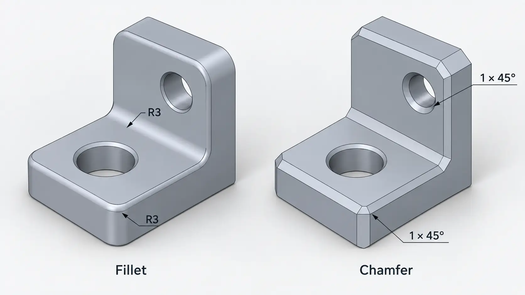
For CNC-machined parts, the location of the feature matters just as much as its shape. An internal radius inside a pocket can influence cutter diameter and machining stability, while a chamfer at the end of a shaft may exist mainly to help the shaft enter a bearing or bushing. The practical difference between a fillet and chamfer therefore comes down to what that specific edge needs to do.
This guide compares fillets and chamfers from a mechanical design and CNC machining perspective, including stress, tooling, manufacturing cost, assembly, and drawing requirements.
What Is a Fillet?
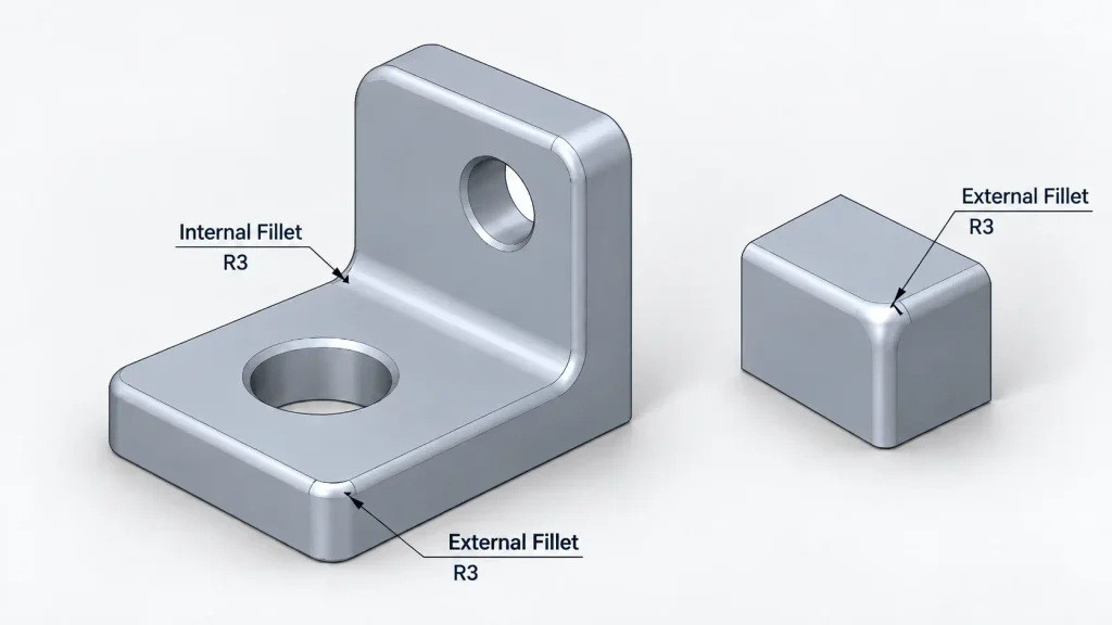
In engineering, a fillet is a rounded transition between two intersecting surfaces, normally defined by a radius such as R1, R3, or R5. Fillets may be internal, where the radius forms a concave corner, or external, where it rounds the outside edge of a component. A filleted corner is often used where an abrupt change in geometry would create an undesirable stress concentration. At a shoulder, rib base, wall transition, or change in section thickness, an appropriate radius allows the geometry to change more gradually instead of meeting at a sharp intersection.
Internal fillets also have a direct relationship with CNC milling. A rotating end mill cannot produce a perfectly sharp vertical inside corner because the cutting tool itself is round, so a radius naturally remains where two milled walls meet. The design question is often not whether an internal fillet should exist, but how small that radius actually needs to be. A very small internal radius can restrict cutter diameter, and if the corner is also deep inside a pocket, the required tool may need to be both small in diameter and long in reach. That combination reduces tool rigidity and can make machining more sensitive to deflection, vibration, and surface-finish variation.
External fillets create a different manufacturing condition because the cutter normally approaches an outside edge from open space. Cutter diameter is therefore not constrained in the same way. An external filleted edge can still be useful for load distribution, clearance, handling, or appearance, but it does not need to be added automatically to every outside edge.
What Is a Chamfer?
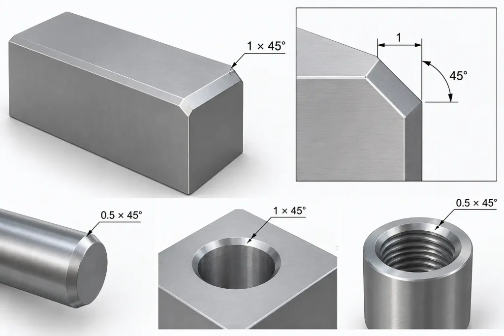
A chamfer is a flat angled surface that replaces the intersection between two surfaces. A common engineering drawing callout such as 1 × 45° specifies both its size and angle, although chamfers can use other angles when the function of the feature requires them. Unlike a fillet, which creates a continuous radius, a chamfer creates a straight inclined face, so its geometry is normally controlled by a width, an angle, or both rather than by a radius.
This difference becomes important once the edge performs a mechanical function. A fillet produces a smooth transition between adjacent surfaces, while a chamfer establishes a predictable entry geometry. That makes chamfers particularly useful where another component needs to approach or pass over an edge, such as at the end of a shaft, around a hole entrance, or at the beginning of a threaded feature.
Chamfers are also commonly used on exposed machined edges where the main requirement is simply to remove sharpness or burrs. In those cases, the chamfer may have no structural role at all. Its purpose is to make the edge easier to handle, less vulnerable to minor damage, or more suitable for assembly.
What Is a Chamfered Edge?
A chamfered edge is an edge that has been intentionally replaced by a flat angled face rather than being left sharp. The chamfer may be functional, such as an assembly lead-in, or it may simply be used to remove a sharp corner after machining. Chamfered edges and corners are common at shaft ends, hole entrances, threaded features, locating pins, and exposed machined edges.
On a shaft or locating pin, the angled edge can help the component enter a mating bore before the full diameter engages. Around a drilled or threaded hole, a chamfer can remove the sharp entrance edge while also helping guide a fastener into position. The same geometry may therefore serve both a manufacturing purpose, by removing a burr, and an assembly purpose, by creating a controlled lead-in.
The function of the edge determines how closely it needs to be controlled. A small chamfer used only for deburring may be covered by a general edge-break requirement, while a chamfer that controls assembly, seating, clearance, or another functional interface normally needs a defined size and angle. A functional chamfered edge and a simple deburred edge may look similar, but they do not create the same manufacturing or inspection requirement.
Fillet vs Chamfer: Key Differences
The visible difference between a fillet and chamfer is straightforward: one uses a radius and the other uses an angled face. The more important differences appear when the edge affects loading, cutter selection, assembly, clearance, or the manufacturing route.
| Factor | Fillet | Chamfer |
|---|---|---|
| Geometry | Rounded radius | Flat angled face |
| Typical callout | R2, R3, R5 | 0.5 × 45°, 1 × 45° |
| Loaded transition | Usually preferred | Less gradual |
| Internal CNC corner | Common and often unavoidable | Less common |
| Assembly lead-in | Limited | Very effective |
| External edge break | Possible | Usually straightforward |
| Tool-size influence | Important for internal radii | Usually low on accessible edges |
| Common role | Load transition, internal corner | Assembly, deburring, edge entry |
Shape and Geometry
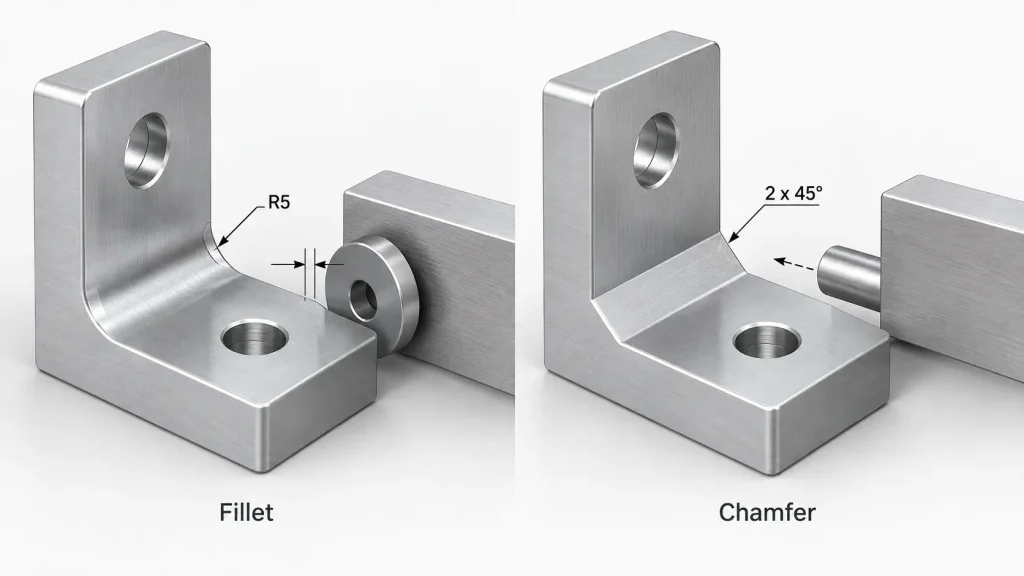
A fillet forms a continuous curved transition between adjacent surfaces. Increasing the radius makes the geometric change more gradual, but it also occupies more space around the corner. That becomes important when a bearing, washer, seal, mating block, or nearby wall needs to approach the transition closely. A larger radius may be structurally desirable, but it can create a clearance problem if the mating component cannot sit against the adjacent face.
A chamfer introduces a flat face instead. Rather than controlling the feature by radius, the designer normally controls its width and angle. This makes a chamfer particularly useful when the edge needs to establish a predictable entry geometry rather than a smooth structural transition. On a small exposed edge, a fillet and chamfer may appear almost interchangeable, but once the edge carries load, controls clearance, or interacts with another component, the two geometries no longer perform the same function.
Strength and Stress Concentration
A fillet is generally the better starting point when a corner lies on a meaningful load path. At an abrupt shoulder or change in section thickness, stress tends to increase locally around the geometric transition. Under bending, torsion, vibration, or repeated loading, that localized increase can become important for fatigue performance. A radius makes the change in geometry more gradual and distributes the transition over a larger region of material, which is why fillets are commonly used around loaded internal corners, rib bases, shaft shoulders, and other structural transitions.
A chamfer removes the original sharp tip, but the angled surface still meets the neighboring surfaces through two separate geometric transitions. It can be preferable to leaving a completely sharp corner, but it does not create the same continuous transition as a fillet. This does not mean a fillet automatically makes every part stronger. The actual effect depends on the radius, surrounding section geometry, material, load direction, and how the part is constrained.
A larger fillet is not automatically better either. A large shoulder radius may prevent a bearing, washer, seal, or spacer from seating against the adjacent face. In that situation, the radius and mating geometry need to be considered together. A compatible chamfer or relief on the mating component may provide the required clearance without unnecessarily reducing the structural radius.
CNC Machining and Tooling
The most important manufacturing difference between chamfer vs fillet appears at internal CNC-milled corners. Because an end mill is round, it naturally leaves a radius where two vertical walls meet. If the drawing specifies a very small internal fillet, the finishing cutter must be small enough to enter that radius. When the same corner lies deep inside a pocket, the cutter may also require additional reach. A small-diameter, long-reach tool is less rigid than a larger, shorter cutter, which increases sensitivity to tool deflection, vibration, chatter, and surface-finish variation.
The relationship between cutter radius and part radius also matters. If the cutter radius is very close to the specified internal corner radius, tool engagement can increase sharply as the cutter enters the corner. Cutting load rises while the tool is changing direction, which can increase deflection or chatter. This is why specifying the smallest theoretically machinable radius is rarely the best design target. If the mating geometry allows more space, increasing the internal radius can permit a larger and stiffer end mill while giving the cutter a smoother path through the corner. The important pocket walls, floor, hole locations, or mating surfaces may remain unchanged while the machining process becomes more stable.
External fillets behave differently because the tool approaches an outside edge from open space rather than having to fit inside the radius. The manufacturing decision is therefore more about how the rounded profile will be generated. A functional external radius may justify a corner-rounding tool or contoured toolpath, while a non-critical outside edge that only needs to be broken can often be produced more directly with a chamfer.
Manufacturing Cost
The cost difference between a fillet and chamfer depends less on the name of the CAD feature and more on whether the geometry changes the machining route. A standard chamfer on an accessible outside edge can often be produced efficiently with a common chamfer mill, and one tool may be able to process several edges or several similar chamfer sizes without significantly changing the overall machining strategy.
An internal fillet is different because the end mill already leaves a radius in the corner. If the specified radius is compatible with the cutter already being used to machine the pocket, the fillet itself may add very little machining time. Cost begins to increase when the radius forces the use of another cutter. A small internal fillet may require a smaller finishing tool, and a deep corner may require that tool to have additional reach. Tool changes, lower cutting parameters, and longer finishing operations can then increase cycle time.
The useful cost question is therefore not simply whether a fillet is more expensive than a chamfer. It is whether the edge geometry forces a different cutter, toolpath, setup, or cycle time. A small internal radius can be expensive if it dictates a small, long-reach tool, while a larger radius may add almost nothing beyond the normal pocket-finishing operation. This relationship between feature geometry and process planning is one reason apparently minor details can have a disproportionate effect on CNC machining cost.
Assembly and Mating Features
Chamfers are particularly useful where two components need to find each other during assembly. Consider a shaft entering a bearing or bushing. With a square shaft end, even a small amount of initial misalignment can cause the edge to catch against the bore. A controlled chamfer creates a tapered entry region, allowing alignment to improve before the full shaft diameter engages. The same principle applies to locating pins, dowel holes, press-fit components, and many threaded features.
A chamfer around a hole can remove the entrance burr while also providing clearance for the mating part, and a shaft chamfer can reduce the chance of edge damage during repeated installation. These are functional chamfered edges rather than cosmetic edge treatments. Their size still needs to match the actual interface. A chamfer that is too small may provide little useful lead-in, while one that is unnecessarily large can shorten the available bearing length, reduce thread engagement, decrease sealing area, or remove useful contact surface.
Fillets can create a different assembly problem. A shoulder radius may prevent a bearing, spacer, or washer from seating completely against the adjacent face even when the nominal diameters and lengths are correct. The mating edge must provide enough clearance to avoid contacting the fillet first. This is why fillets and chamfers at mating interfaces should be considered as part of the assembly rather than as isolated CAD features.
Engineering Drawing and Inspection
A fillet is normally dimensioned by its radius, such as R2 or R5, while a chamfer is commonly specified using a distance and angle, such as 1 × 45°. Once these dimensions appear on the engineering drawing, the edge geometry itself becomes a controlled feature. Manufacturing is no longer being asked simply to remove a burr; it is being asked to produce a defined geometric requirement.
That is different from a general instruction such as Break sharp edges. A general edge-break note normally communicates that unacceptable burrs and sharp corners should not remain, but it does not necessarily require every edge to become a precisely measured 0.5 × 45° chamfer. Turning every non-critical edge into a tightly controlled feature can add machining and inspection work without improving how the part functions.
The same principle applies to fillets. A fatigue-critical shoulder radius may require a clearly defined dimension because changing it could influence the load transition, while an external rounded edge added only for handling may not need the same level of dimensional control. Good engineering drawings distinguish between function-critical edge geometry and general edge treatment instead of applying identical requirements throughout the part.
When Should You Use a Fillet?
A fillet is usually appropriate when the corner forms part of a loaded structural transition. Shoulders, rib bases, changes in section thickness, and other fatigue-sensitive areas often benefit from avoiding an abrupt geometric change, provided the radius still leaves enough clearance for mating components. In these locations, the fillet is part of the mechanical design rather than simply a way to remove a sharp edge.
Fillets also make sense at CNC-milled internal corners because some radius is already unavoidable with conventional end milling. The design opportunity is therefore not to eliminate the radius but to select one that works with practical tooling. If the functional geometry can tolerate a larger fillet, increasing the radius may allow a larger cutter and improve machining stability without changing the important surfaces of the pocket.
External fillets deserve more selective use. A rounded outside edge can be justified where it controls load transfer, contact, clearance, handling, or appearance. If none of these functions exist, adding fillets to every external edge may increase machining complexity without adding useful performance.
When Should You Use a Chamfer?
A chamfer is usually the more natural choice when an edge needs to guide assembly. Shaft ends, locating pins, hole entrances, bushings, and threaded features commonly use angled lead-ins because the geometry helps mating components approach each other without catching on a sharp edge. In these locations, the chamfer serves a direct functional purpose.
Chamfers are also well suited to many non-critical external edges. If an outside corner only needs to be safer to handle, easier to deburr, or less vulnerable to minor edge damage, a small chamfer can provide the required result without introducing a fully rounded profile. Manufacturing simplicity is therefore a valid reason to choose a chamfer when the edge has no structural requirement for a fillet.
When the chamfer performs an assembly function, however, its size should come from the mating geometry rather than from a universal default. A shaft lead-in that is too small may provide little benefit, while an unnecessarily large one can shorten the usable cylindrical surface. The same reasoning applies to hole entrances, threads, and other controlled mating features.
Chamfer vs Bevel: Is There a Difference?
The terms chamfer and bevel are sometimes used interchangeably, but they do not always describe exactly the same type of geometry. A chamfer normally refers to an angled face added where two surfaces would otherwise form a sharp edge. In mechanical parts, chamfers are commonly used for assembly lead-ins, hole entrances, deburring, and controlled external edges.
A bevel is a broader term for an inclined or sloped surface and does not necessarily refer to a small edge treatment. Depending on the application, a bevel may describe a much larger angled face, such as an edge prepared for welding. In practical mechanical design, the terminology matters less than the actual drawing requirement. If the angle, width, depth, and location of the feature affect function, they should be specified clearly rather than relying on the words bevel or chamfer alone.
How to Choose Between a Fillet and Chamfer
There is no need to choose one edge treatment for an entire machined part. Most well-designed components use different solutions in different locations because each edge performs a different job.
| Edge Requirement | Better Starting Choice |
|---|---|
| Loaded internal transition | Fillet |
| Fatigue-sensitive shoulder | Fillet |
| CNC-milled pocket corner | Fillet |
| Shaft or locating-pin lead-in | Chamfer |
| Thread or hole entrance | Chamfer |
| Non-critical external sharp edge | Chamfer or edge break |
| Functional rounded external profile | Fillet |
For an internal CNC corner, first consider whether the radius can be increased without interfering with the mating geometry. A larger permitted radius may allow a larger cutter and make the feature easier to machine consistently. For a loaded shoulder, consider both stress transition and assembly clearance. Increasing the radius while ignoring the mating component can simply move the problem from structural performance to fit.
When another component approaches an edge during installation, consider whether a chamfer provides a useful lead-in. Its width and angle should relate to the mating geometry rather than simply repeating the same default chamfer throughout the design. If an outside edge has no structural, assembly, sealing, clearance, or appearance requirement, it may only need a general edge break rather than a tightly controlled fillet or chamfer.
Deep pockets and small internal radii deserve particular attention before the geometry is frozen because cutter diameter, reach, and stiffness can change quickly as the permitted radius decreases. The available CNC milling strategy should therefore be considered together with the CAD geometry rather than after the drawing has already been released.
Conclusion
A fillet and a chamfer both remove sharp geometry, but they solve different engineering problems. A fillet creates a rounded transition that is useful around loaded features and is naturally associated with CNC-milled internal corners, while a chamfer creates an angled entry that is particularly effective at mating features and provides a practical way to treat many non-critical external edges.
The better choice depends more on the function and location of the edge than on a general rule that one feature is stronger, cheaper, or easier to manufacture. A structural shoulder, an internal pocket corner, a bearing lead-in, and an exposed outside edge may all require different treatments even when they appear on the same machined component. For CNC-machined parts, edge geometry should therefore be considered together with loading, cutter access, assembly clearance, and inspection requirements rather than treated as a cosmetic CAD detail.
FAQ
A fillet is generally more suitable for a loaded geometric transition because the radius creates a smoother change in section and can reduce localized stress concentration. The actual effect still depends on the radius, surrounding geometry, material, section thickness, and direction of loading, so a fillet should not be treated as an automatic strength improvement in every situation.
Often, but not always. A conventional external chamfer may be straightforward to machine, while an internal fillet that already matches the cutter used for a pocket may add very little extra cost. Cost increases when the edge requires additional tools, smaller cutters, special contouring, extra toolpaths, or longer machining time.
Not as a direct substitute in a conventional milled pocket. Where two vertical internal walls meet, the round end mill naturally produces a radius. Replacing that corner with a chamfer changes the geometry and may require a different machining strategy or additional tool access. If the goal is simply to make the corner easier to machine, increasing the permitted internal radius is usually more useful.
No. A 45-degree chamfer is common for general edge breaking and many assembly features, but other angles can be used when required by the mating geometry, countersink, sealing interface, or another functional requirement.
A chamfer is a defined geometric feature with a specified size and often a specified angle. An edge break is a broader requirement to remove unacceptable sharpness or burrs. A functional chamfer may therefore require controlled machining and dimensional inspection, while a non-critical edge break normally does not require the same level of geometric control.




