

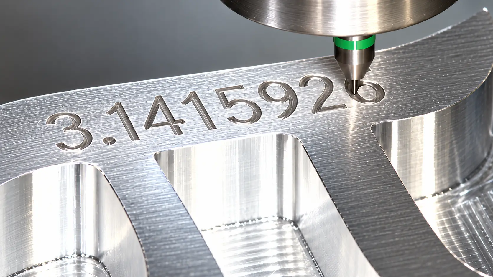
This text milling guide explains how CNC machines cut letters and markings into parts, from selecting a machining method and cutter to choosing fonts, materials, and cutting depth. It also covers the common problems that affect readability and the design choices that help prevent them.
What Is Text Milling?
Text milling, also called CNC text engraving or lettering, uses a rotating cutting tool to machine letters, numbers, symbols, and simple logos into a part. CAD/CAM software turns the text geometry into toolpaths, which guide the cutter across the workpiece at a specified depth.
Because the tool removes material, the marking has physical depth. Manufacturers use text milling to add part numbers, serial codes, control labels, safety information, and branding to metal and plastic components. The lettering can be recessed into the surface or raised by machining away the material around it.
How Does Text Milling Work?
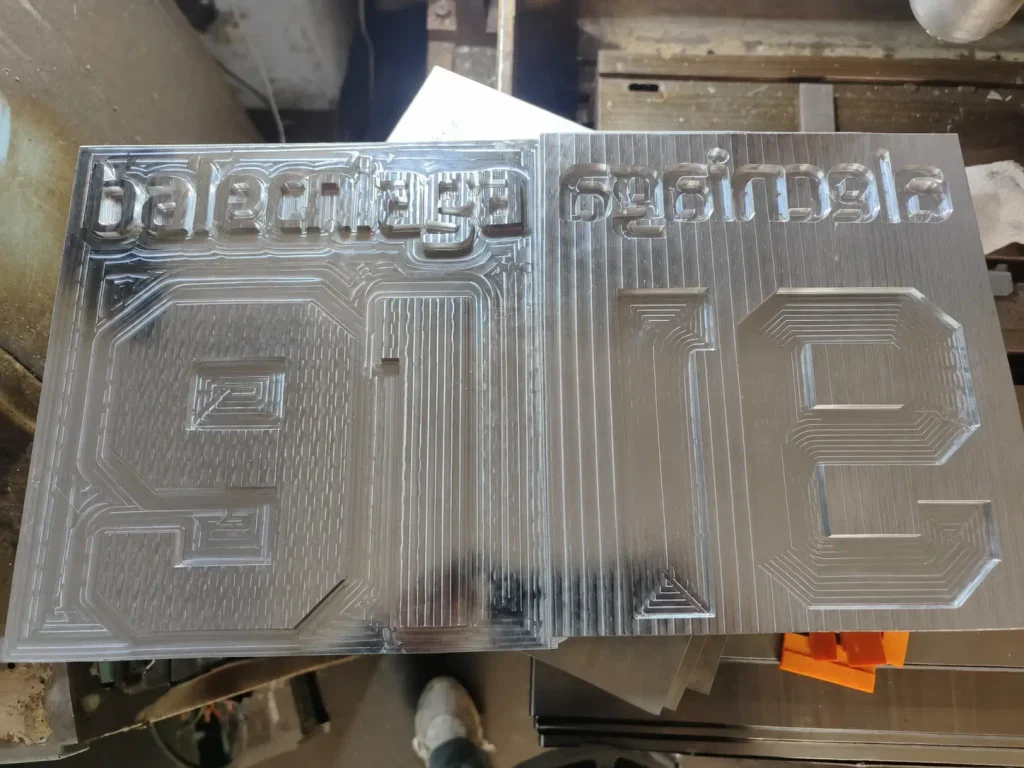
Text milling turns digital lettering into cutting paths that a CNC machine can follow. Before machining begins, the text must have a defined size, position, orientation, and shape. The selected toolpath then determines whether the finished characters appear as narrow lines, outlines, or wider recessed letters.
1. Prepare the Text Geometry
The text is placed on the part model or drawing in CAD software. Standard lettering may be created directly in the model; a logo or custom font may be supplied as vector outlines so its shape does not change when files move between programs. At this stage, the designer also decides whether the text will be cut into the surface or left raised above the surrounding material.
2. Program the Cutting Path
In CAM software, the programmer selects a cutter and generates a path for the intended lettering. A centerline path follows the middle of each character stroke. A contour path follows its boundary, while a pocket path removes material within a closed letter shape. The CAM program calculates the tool movements and produces machine instructions, including the cutting positions, spindle speed, and feed rate.
3. Set Up and Mill the Part
The workpiece is held securely, and the cutter is positioned relative to the surface where the text will be machined. The CNC machine then moves the rotating tool along the programmed path to remove material. After cutting, the operator checks the letters for readable spacing, consistent depth, and burrs, particularly where small strokes meet or characters contain narrow enclosed spaces.
Machines and Cutting Tools for Text Milling
Machine access and cutter geometry determine what lettering can be produced on a part. The machine must reach the marking surface and hold the workpiece steady. The cutter must fit the smallest strokes and spaces in the font without damaging its tip.
CNC Machines
CNC milling machines and vertical machining centers can add part numbers, serial codes, and labels to housings, brackets, and panels, often while the part is already set up for other machining operations. CNC routers are commonly used for larger lettering on wood and plastic signs.
The shape and position of the marking face affect the setup. A flat face is easier to cut at a consistent depth. Text on an angled or curved face may require another setup or a toolpath that follows the surface to keep the letters even.
Cutting Tools
The lettering style guides tool selection:
V-shaped cutters produce narrow grooves. Cutting deeper makes the stroke wider, so surface height and depth control are especially visible in small letters.
Small flat end mills trace outlines or clear material inside wider characters. Their diameter must fit the tightest spaces in the font.
Ball nose cutters leave rounded grooves where a softer letter profile is acceptable.
A tool that cannot enter the enclosed space of an A, B, or R will leave that detail incomplete. Using a smaller tool can preserve the shape, but it may also increase machining time and sensitivity to tool wear.
Tool Setup and Cutting Conditions
Many CNC systems offer built-in engraving canned cycles like G47 and CYCLE60 to generate character toolpaths automatically. However, spindle speed, feed and cutting depth still require manual tuning by material and tool. Fine lettering exposes spindle runout, tool wear and workholding shift, which cause uneven marks, burrs or broken tools. Validate parameters on trial parts before full production, as one parameter recipe cannot cover all fonts and materials.
| Material | Tool | Spindle Speed | Engraving Feed | Plunge Feed | Max Marking Depth |
|---|---|---|---|---|---|
| 6061 Aluminum | 2-flute carbide V-bit | 12,000–15,000 RPM | 400–600 mm/min | 80–120 mm/min | 0.1–0.4 mm |
| Stainless Steel | Micro carbide engraving tool | 8,000–10,000 RPM | 200–350 mm/min | 50–80 mm/min | 0.05–0.2 mm |
| Engineering Plastic | Single flute V-cutter | 7,000–9,000 RPM | 500–800 mm/min | 100–150 mm/min | 0.2–0.5 mm |
What Materials Can Be Text Milled?
Text milling can be used on metals and plastics that are suitable for CNC machining. Material choice affects the cutter, cutting conditions, and the appearance of the finished letters. The same font and toolpath may produce clean edges in one material but burrs or softened details in another.
Aluminum: Cuts readily and is commonly used for marked housings, panels, and brackets. Burrs around small letters still need attention, particularly when the text sits near an edge.
Stainless steel: Can produce durable markings, but small cutters require careful control of tool wear and cutting forces. Fine details may call for a larger font or a different tool.
Brass: Machines well for labels, instrument parts, and decorative lettering. Its surface appearance can make both the cut and the surrounding finish important to the final look.
Engineering plastics: Materials such as POM and acrylic can carry milled text, but their cutting behavior differs. Heat may smear a plastic groove, while brittle materials may chip at the edges of small characters.
Surface finishing can change the result after milling. Blasting may soften a shallow mark, and a thick coating may fill narrow grooves. On anodized aluminum, machining before or after anodizing also changes the color contrast and whether the cut surface retains the anodized layer. The intended finished appearance should guide the order of operations.
If you need readable text on a custom machined part, send your drawing to ZH Precision. We can review the material, letter size, and surface finish to identify details that may burr, chip, or become difficult to read after finishing, then suggest adjustments before machining.
Where Is Text Milling Used?
Text milling is used when information needs to be cut directly into a component. The marking may identify the part, help someone use it, or show how it should be positioned. Its location and size should suit that purpose: a serial code on a small housing has different requirements from labels on a control panel.
Part identification: Part numbers, serial numbers, and revision codes help distinguish similar components during inspection, installation, and maintenance.
Operating labels: Words and symbols beside switches, ports, and controls identify their functions without relying on an attached label.
Scales and position marks: Milled lines, numbers, and arrows show settings, movement ranges, or assembly orientation.
Product markings: A name or simple logo can be machined into a visible face when the design calls for lettering with physical depth.
For individually numbered parts, the fixed text and changing serial code may need separate programming or marking steps. That distinction matters when planning a production run: repeating one label on every part is simpler than milling a different code into each one.
How to Design Readable Milled Text
A font that looks clear on a screen may lose its shape when cut into metal or plastic. Before setting a character height, check its narrowest strokes, the spaces inside its letters, and the cutter needed to machine them. The finished surface treatment also matters: a shallow mark that is easy to read straight off the machine may be less distinct after blasting or coating.
Font and Character Size
Simple fonts with open letter shapes are easier to mill at small sizes. Decorative strokes and tight spacing can leave too little room for the cutter, especially inside characters such as A, B, e, and 8. Increasing the overall height helps only if the strokes and enclosed spaces grow enough for the selected tool.
For a custom typeface or logo, supply vector outlines along with the drawing. This preserves the intended shapes if the recipient does not have the same font installed.
Depth and Placement
Depth affects more than how visible the mark appears. With a V-shaped cutter, a deeper cut produces a wider stroke; too much depth can cause neighboring strokes to merge. For flat end mills, deeper text adds cutting time and may require more than one pass. The appropriate depth depends on the material, tool, letter geometry, and required appearance.
Place text where the cutter can reach it without crossing holes, edges, sealing faces, or other functional features. If its alignment matters, dimension its position on the drawing instead of relying on how it appears in a rendered model.
Appearance After Finishing
The marking should be evaluated in the condition in which the part will be used. Bead blasting can soften fine edges, while powder coating can fill narrow grooves. Milling through an existing anodized layer exposes the aluminum beneath it and changes both the contrast and the surface protection inside the letters. Define the desired appearance after finishing so the machining and finishing sequence can be planned accordingly.
Common Text Milling Problems
Problems with milled lettering often become obvious only after the first part is cut. Inspecting that part reveals whether the programmed text, cutter, and setup produce the intended result before the marking is repeated across a batch.
Closed or blurred characters: If the cutter cannot enter a small enclosed space, letters such as B and R lose their shape. Enlarge the text, open up the font, or use a smaller cutter if the setup can support it.
Uneven stroke width: With a V-shaped cutter, variation in surface height changes the width of the groove. Check the marking face, workholding, tool position, and programmed depth before adjusting the font.
Burrs and rough edges: A worn cutter, unsuitable cutting conditions, or poor chip removal can leave material along the strokes. Address the cutting cause first; heavy deburring may round off small letters.
Missing detail after finishing: Blasting can reduce the definition of a shallow mark, while coating can cover fine grooves. Inspect a finished sample and adjust the text geometry or the order of operations if the marking no longer reads clearly.
The correction depends on the defect. Making every letter deeper will not solve a cutter that cannot fit inside the font, and switching to a smaller tool will not correct uneven depth across a tilted surface.
Text Milling vs. Other Marking Methods
Text milling is one way to put information on a part, but it is not the best fit for every marking. The choice depends on whether the text needs physical depth, how much detail it contains, how often it changes, and what will happen to the surface during use.
| Method | How the mark is made | Often suitable for |
| Text milling | A rotating cutter removes material to form the characters. | Recessed lettering on machined parts, particularly when the mark can be cut during an existing CNC setup. |
| Laser marking | A laser changes or removes material at the surface; the depth and appearance depend on the process. | Fine details, dense codes, and variable information such as individual serial numbers. |
| Stamping | A shaped tool presses characters into the material. | Repeated, simple markings on parts that can withstand the forming force. |
| Printing or labels | Ink or a separate label carries the information. | Color, large amounts of information, or markings that may need to change. |
For a short part number on an accessible machined face, milling may be straightforward. A different serial number on every part can make laser marking more practical because the information changes without requiring a new cutting path for each component. If abrasion, cleaning, or a later coating process matters, compare samples in their finished condition rather than choosing from the marking method alone.
What to Specify on a Text Milling Drawing
Show the exact wording and marking location on the part drawing. Include the text orientation, character height, and whether the letters should be recessed or raised. If the appearance depends on a particular font or logo, provide its vector outlines so the character shapes are preserved.
For markings where depth, position, or appearance matters, define those requirements explicitly. Also state the material and final surface finish. A note such as “text must remain legible after powder coating” gives the manufacturer a useful finished-part requirement; the CAD model alone may show the letters without revealing that the coating could fill them.
Serial numbers need one more instruction: identify which characters change from part to part and how the sequence is assigned. That allows the changing information to be planned and checked separately from text that is identical on every component.
FAQ
Yes, if the machine and setup can keep the cutter at the intended position relative to the surface. A toolpath made for a flat face may cut too deeply in one area and miss another on a curved part. The surface shape should be included in the CAD model so the machining approach can be planned.
Yes. Instead of cutting into each character, the cutter removes material around it. Raised letters generally take longer to machine because a much larger area must be cleared. Narrow strokes may also be vulnerable to damage during machining or use.
Milling before anodizing allows the anodized finish to cover the cut letters. Milling afterward removes the anodized layer inside the strokes and exposes the underlying aluminum, which can create visible contrast. The choice depends on the required appearance and the environment in which the part will be used.
There is no single minimum character height. A letter’s narrowest stroke and enclosed spaces matter as much as its overall height. The achievable size depends on the cutter, material, surface condition, and required readability, so very small text should be checked with a sample.




