

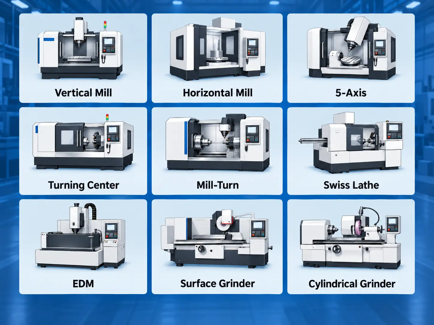
For engineers and buyers, knowing the names of the machines is only the starting point. The more useful distinction is what each machine is designed to do and what kinds of parts it handles efficiently. This guide explains the main types of CNC machines, how they differ, and where each type is commonly used.
What Are the Main Types of CNC Machines?
Most CNC equipment can be grouped by the way it removes material and controls movement between the cutting tool and workpiece.
| CNC Machine Type | How It Works | Common Parts and Features |
|---|---|---|
| CNC Milling Machine | A rotating cutting tool removes material from a clamped workpiece | Housings, brackets, plates, pockets, holes |
| 5-Axis CNC Machining Center | Adds rotary movement to conventional milling axes | Multi-face parts, angled features, complex surfaces |
| CNC Lathe / Turning Center | The workpiece rotates against a cutting tool | Shafts, bushings, sleeves, flanges |
| Mill-Turn CNC Machine | Combines turning and milling in one machine | Round parts with flats, slots, or cross holes |
| Swiss-Type CNC Lathe | Bar stock moves through a guide bushing close to the cutting zone | Long, slender, small-diameter parts |
| CNC Router | A high-speed rotating cutter moves over a large working area | Plastics, composites, panels, softer materials |
| CNC EDM Machine | Electrical discharge removes conductive material | Narrow slots, intricate profiles, difficult internal features |
| CNC Grinding Machine | An abrasive wheel removes small amounts of material | Hardened parts and precision finished surfaces |
| CNC Cutting Machine | Laser, plasma, or waterjet follows a programmed profile | Sheet and plate components |
These categories are useful, but CNC machine terminology can overlap. A 5-axis machine, for example, is usually still a milling machine. The term “5-axis” describes how the machine can move rather than a completely different cutting process.
CNC Milling Machines
CNC milling machines use rotating cutting tools to remove material while the workpiece is held in a fixture, vise, or directly on the machine table. Controlled movement along the machine axes allows the cutter to create flat faces, pockets, holes, slots, contours, and three-dimensional surfaces.
This makes milling a common choice for prismatic parts such as housings, brackets, plates, fixtures, structural components, and many mechanical parts that do not revolve around a single centerline.
The basic cutting principle is similar across milling machines, but their physical arrangement can differ significantly.
Vertical Machining Centers
A vertical machining center, commonly called a VMC, has a spindle oriented vertically above the workpiece. The cutter approaches primarily from the top while the machine moves the tool or table along the X, Y, and Z axes.
VMCs are widely used because they work well for a broad range of general milling operations. Parts with top-facing pockets, drilled holes, profiles, bores, and machined surfaces can often be produced efficiently with straightforward workholding.
Features on other sides of the part may require the workpiece to be repositioned, rotated, or mounted in another fixture.
Horizontal Machining Centers
A horizontal machining center uses a spindle oriented horizontally rather than vertically. Parts are commonly mounted on pallets, tombstones, or multi-sided fixtures so several surfaces can be presented to the cutting tool.
This arrangement is particularly useful for components that require machining on several sides or for production where reducing manual handling between operations is important. The horizontal spindle orientation can also improve chip evacuation because chips are less likely to remain inside upward-facing pockets.
The choice between vertical and horizontal machining is therefore not simply a question of which machine is more capable. Part orientation, tool access, workholding, production volume, and the number of surfaces being machined all influence the decision.
5-Axis CNC Machining Centers
A 5-axis machining center typically combines the three linear X, Y, and Z axes of conventional milling with two additional rotary axes. Depending on the machine design, these rotary movements may come from a tilting table, a rotating table, the spindle head, or a combination of these mechanisms.
The extra movement allows the cutter to approach the workpiece from more directions. Parts with angled holes, multiple machined faces, complex surfaces, or difficult tool access can often be completed with fewer repositioning operations than on a conventional 3-axis machine.
For example, a housing may require machining on its top, sides, and an angled interface. A 3-axis machine may still be able to make the part, but several individual setups could be needed. A 5-axis machine can often orient the workpiece so more of those features remain accessible in one clamping.
This does not mean every complex-looking part requires 5-axis machining. If the geometry can be reached easily with conventional workholding and a small number of setups, a 3-axis or 4-axis machine may be more practical.
CNC Lathes and Turning Centers
CNC lathes operate around a different cutting principle. The workpiece rotates in the spindle while cutting tools feed along or across the rotating material.
This makes turning particularly suitable for parts whose main geometry is centered around a common axis. Shafts, bushings, sleeves, pins, spacers, flanges, rollers, and threaded components are typical examples.
Common turning operations include facing, outside-diameter turning, boring, grooving, threading, drilling, and parting. Modern CNC turning centers may also include driven tools, additional axes, or secondary spindles, allowing operations that go beyond basic turning.
The presence of a round feature alone does not mean a part should be turned. A milled housing may contain many circular holes and bores. Turning becomes the natural choice when the overall part geometry is predominantly rotational.
Mill-Turn CNC Machines
Some parts combine substantial turning and milling requirements.
A cylindrical component may contain concentric diameters and threads but also require flats, radial holes, slots, keyways, or other features that do not share the main rotational axis. On separate machines, the part may first be turned, removed from the lathe, and then positioned again on a milling machine.
Mill-turn CNC machines combine turning and milling capability in the same machine. Driven tools and additional axes allow many off-axis features to be machined without transferring the component to a separate machining center.
This can be especially useful when the relationship between turned and milled features is important. Reducing the number of times a part must be removed and re-established in another fixture can simplify handling and reduce setup-to-setup variation.
For a simple shaft or sleeve, however, a conventional turning center may still be the more efficient choice. Mill-turn equipment becomes more valuable as the number and importance of secondary milled features increase.
Swiss-Type CNC Lathes
Swiss-type lathes are designed differently from conventional turning centers. Bar stock passes through a guide bushing while a sliding headstock feeds the material through the cutting area.
The cutting tools operate close to the guide bushing, which keeps the workpiece supported near the point where machining occurs. This arrangement helps control deflection when producing long, slender parts.
Swiss-type machines are therefore commonly used for small-diameter components with relatively high length-to-diameter ratios. Pins, shafts, connectors, sleeves, and other precision bar-turned components can be well suited to this machine architecture.
The advantage comes from the way the workpiece is supported, not simply from the machine being more precise than a conventional lathe. For short or larger-diameter components, a standard turning center may be more appropriate.
Other Types of CNC Machines
CNC control is used far beyond milling and turning. Several other machine types use programmed movement but remove material in different ways.
CNC Routers
CNC routers use rotating cutting tools and can appear similar to milling machines, but they are generally designed around larger working areas and relatively high spindle speeds.
They are commonly used for plastics, composites, wood, foam, sheet materials, and some aluminum applications. Machine rigidity, spindle power, tooling, and intended cutting loads usually differ from those of heavy metal-cutting machining centers.
CNC EDM Machines
Electrical discharge machining, or EDM, removes material through controlled electrical discharges between an electrode and an electrically conductive workpiece.
Wire EDM uses a continuously moving wire electrode to cut precise profiles through material. Sinker EDM uses a shaped electrode to form cavities and internal geometry.
EDM is useful when conventional cutting tools cannot easily reach a feature, when the material is very hard, or when a narrow internal geometry would be difficult to machine mechanically. Because the process relies on electrical discharge, the material must be conductive.
CNC Grinding Machines
CNC grinding machines remove small amounts of material using abrasive wheels. They are often used after earlier machining operations when tighter final dimensional control, hardened surfaces, or specific surface finishes are required.
Grinding equipment can be configured for cylindrical, surface, internal, and other specialized grinding operations.
CNC Drilling and Boring Machines
Dedicated CNC drilling and boring machines are used when hole production forms a major part of the manufacturing task.
Depending on the equipment, they may be optimized for repeated hole patterns, deep holes, large bores, or large workpieces that would be difficult to position on a conventional machining center.
CNC Laser, Plasma, and Waterjet Machines
Laser, plasma, and waterjet systems also use CNC-controlled motion, but their material-removal methods are very different from conventional machining.
These machines are primarily used to cut two-dimensional profiles from sheet or plate. They are well suited to producing blanks, panels, brackets, and structural profiles before bending, welding, or additional machining.
They are not normally substitutes for milling when a part requires three-dimensional features such as precision bores, pockets, threaded holes, or controlled machined interfaces.
CNC Machine Types vs Axis Configurations
CNC machine classifications can become confusing because several different naming systems are often mixed together.
Milling, turning, grinding, and EDM describe different material-removal processes. Terms such as 3-axis, 4-axis, and 5-axis describe how many controlled directions of movement are available. Vertical and horizontal describe another aspect of the machine arrangement.
| Classification | Examples | What It Describes |
|---|---|---|
| Machining Process | Milling, turning, grinding, EDM | How material is removed |
| Axis Configuration | 3-axis, 4-axis, 5-axis | How the tool and workpiece can move |
| Machine Arrangement | Vertical, horizontal | How the machine is physically configured |
A conventional 3-axis milling machine moves along the X, Y, and Z axes. A 4-axis machine adds rotary movement, which allows the workpiece to be repositioned or machined around an additional axis. A 5-axis machine adds a second rotary degree of freedom, giving the cutting tool access to more workpiece orientations.
This is why a 5-axis machining center can appear in a practical list of CNC machine types while still technically belonging to the milling-machine family.
The same distinction applies to vertical and horizontal machining centers. They remain milling machines, but the spindle orientation and workholding arrangement change how the workpiece can be presented to the cutter.
How to Choose the Right CNC Machine for a Part
Machine selection usually begins with part geometry.
A component dominated by concentric diameters, bores, threads, and cylindrical surfaces is usually a turning candidate. A bracket or housing containing pockets, holes, flat faces, and machined interfaces is more naturally suited to milling.
Parts that combine these two geometry types require a closer look.
| Part Geometry | Machine Commonly Considered |
|---|---|
| Mostly rotational geometry | CNC lathe or turning center |
| Housings, brackets, plates, and other prismatic parts | CNC milling machine |
| Rotational parts with significant off-axis features | Mill-turn CNC machine |
| Multiple angled or difficult-to-access surfaces | 4-axis or 5-axis machining center |
| Long, slender, small-diameter parts | Swiss-type CNC lathe |
| Difficult geometry in conductive materials | CNC EDM |
| Sheet or plate profiles | Laser, plasma, or waterjet |
Tool access is another important consideration. A feature may be simple on the CAD model but difficult to machine if surrounding geometry blocks the cutter or if the tool holder collides with another part of the workpiece.
Setup count also matters. A component that can be produced on a 3-axis machine in two straightforward setups may not gain much from 5-axis machining. If the same component would otherwise require repeated re-clamping to reach several related features, additional axis capability may become more useful.
Part size, material, tolerances, tooling, spindle capability, fixture requirements, production quantity, and inspection strategy can all influence the final choice. For this reason, selecting a CNC machine is usually a process of matching the machine architecture to the part rather than choosing the most advanced equipment available.
Conclusion
The main types of CNC machines differ because they create and access part geometry in different ways.
CNC milling machines are commonly used for prismatic parts, while lathes and turning centers are better suited to rotational geometry. Mill-turn machines combine both processes for parts that contain turned and off-axis features, and Swiss-type machines are designed for long, slender components. Five-axis machining centers extend milling capability by allowing the tool to approach the workpiece from more orientations.
EDM, grinding, routers, and CNC cutting systems serve additional manufacturing requirements where conventional milling or turning may not be the best process.
The right machine is therefore not necessarily the one with the most axes or functions. It is the one that can produce the required geometry with suitable tool access, workholding, accuracy, and production efficiency.
FAQ
The most common types include CNC milling machines, CNC lathes and turning centers, 5-axis machining centers, mill-turn machines, and Swiss-type lathes. Other CNC-controlled equipment includes EDM, grinding, routing, laser cutting, plasma cutting, and waterjet machines.
A CNC mill normally uses a rotating cutting tool while the workpiece remains clamped in a fixture. A CNC lathe rotates the workpiece while the cutting tool feeds against it. Mills are commonly used for prismatic geometry, while lathes are better suited to rotational parts.
In most machining applications, yes. A 5-axis machining center is generally a milling-based machine with three linear axes and two additional rotary axes. The term 5-axis describes the machine’s movement capability rather than a separate material-removal process.
A conventional CNC lathe holds and rotates the workpiece while machining occurs along the unsupported length of the material. A Swiss-type lathe feeds bar stock through a guide bushing so the cutting zone stays close to the support point, which is useful for long and slender components.
Start with the basic geometry. Rotational parts normally favor turning, prismatic parts favor milling, and parts combining turned and milled features may suit mill-turn equipment. Multi-side or angled geometry can justify 4-axis or 5-axis machining, while long, slender parts may be better suited to Swiss turning. Tool access, setup count, tolerance, material, part size, and production quantity should then be considered before choosing the final process.




