

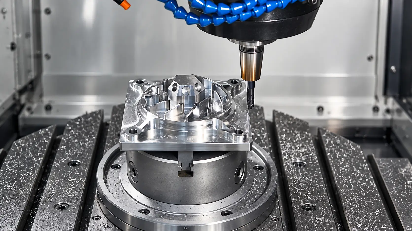
That distinction is important because precision does not come from the CNC machine alone. A machining center may have excellent positioning capability, yet the finished part can still be wrong because of fixture deformation, tool deflection, thermal change, datum transfer, material stress, or an unsuitable inspection method. Precision machining is therefore better understood as a controlled manufacturing process than as a particular class of machine.
What Is CNC Precision Machining?
In practical terms, precision CNC machining means producing critical dimensions and geometric relationships within the limits required by the drawing and maintaining that result consistently from part to part.
This does not mean every dimension on the component needs a tight tolerance. A mounting bracket may contain a bearing bore that requires close control while the surrounding pockets, clearance holes, and exterior surfaces can accept much wider variation. The precision requirement belongs to the feature that controls function, not automatically to the entire component.
Tolerance, accuracy, and repeatability are related but different. Tolerance defines the acceptable range specified on the drawing. Accuracy describes how closely the machined feature approaches its intended value. Repeatability describes whether the process can continue producing that feature within the required range over multiple parts.
A feature that measures correctly once is not enough to demonstrate a stable precision machining process. The manufacturing method must also control the sources of variation that can move that feature during the rest of the production run.
What Actually Controls Precision in CNC Machining?
Machine positioning accuracy is only one part of the total error chain.
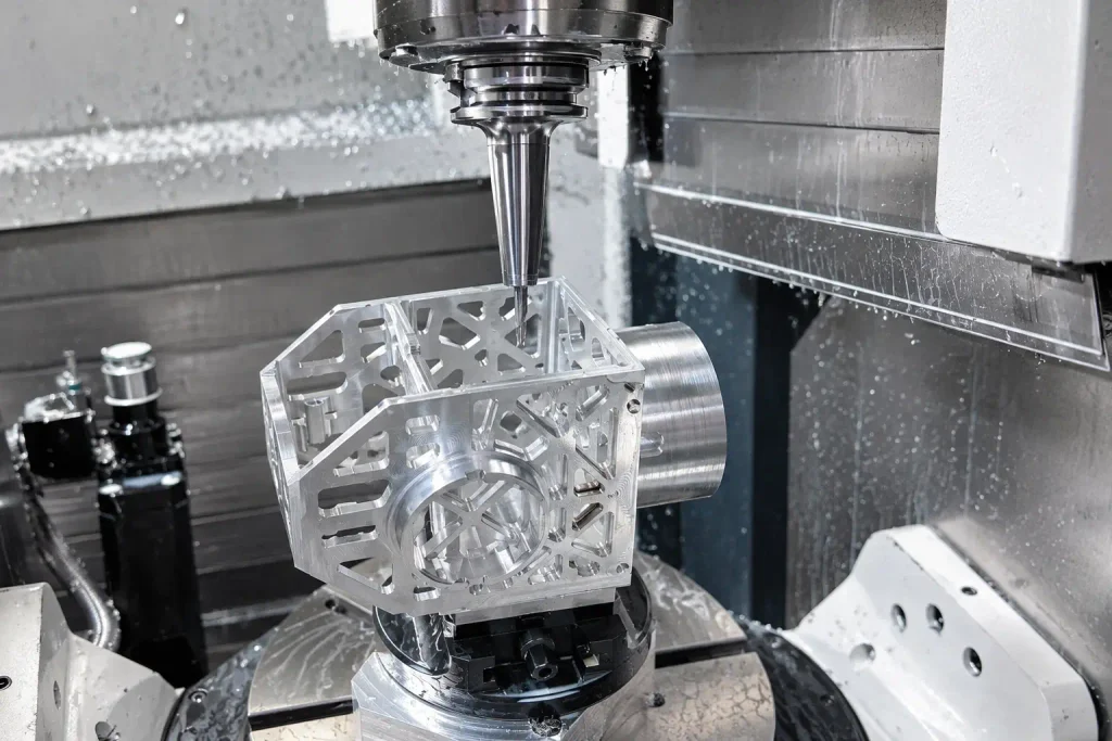
Consider a precision bore in an aluminum housing. Its final diameter and position depend on the machine, but they also depend on how the housing is located, how much clamping force is applied, the stiffness and runout of the cutting tool, how heat develops during machining, whether the material moves as internal stress is released, and how the bore is measured afterward.
Tool reach can change the situation substantially. A short, rigid boring tool working close to the spindle behaves differently from a long tool extending deep into a housing. Cutting force can deflect the longer tool, while heat and chip evacuation become harder to control. The programmed toolpath may be correct while the physical cutting edge does not remain exactly where the program assumes it is.
Workholding introduces another source of variation. Thin walls, rings, housings, and other flexible parts can change shape under clamping pressure. A wall may measure correctly while the component remains clamped, then move after the fixture is released. In that situation, simply reducing the programmed dimension does not solve the real problem. The machining and workholding strategy has to control deformation itself.
Material condition also matters. Rolled plate, extrusions, forgings, and heat-treated stock may contain residual stress. As material is removed, the stress balance changes and the part can move between roughing and finishing operations. For distortion-sensitive components, machining may need to be divided into stages so that most material is removed first and the critical geometry is finished only after the part has become more stable.
This is why a precision capability cannot be described accurately by quoting the machine specification alone.
When Does a Part Actually Need Tight Tolerances?
The useful question is not whether a component is a “precision part.” It is what happens when a particular feature reaches the edge of its allowed variation.
A bearing bore is a simple example. If its diameter becomes too small, the bearing may not assemble correctly. If it becomes too large, the fit may lose the intended retention or alignment. A shaft diameter can create the same type of problem with a clearance or interference fit.
Position can be just as important as size. Two bores may both meet their individual diameter tolerances but still fail assembly because their axes are not positioned correctly relative to each other. A sealing surface can have an acceptable length and width while still leaking because flatness or surface condition is unsuitable.
For this reason, precision requirements are usually concentrated around features such as bearing seats, locating holes, shaft fits, sealing faces, mating datums, valve bores, and other interfaces where dimensional variation changes mechanical function.
A general pocket or clearance feature may not need the same level of control.
A useful drawing review therefore asks:
What will physically happen if this feature reaches either tolerance limit?
If the result could be binding, leakage, excessive clearance, poor alignment, runout, or assembly failure, tighter control may be justified. If the feature still performs normally over a wider range, tightening it usually adds machining and inspection work without improving the component.
How Tight a Tolerance Can CNC Machining Hold?
There is no single tolerance that defines precision CNC machining.
A tolerance that is straightforward on one feature may be difficult on another. The same ±0.01 mm requirement has very different manufacturing consequences depending on feature geometry, stiffness, tool access, material, setup strategy, and inspection access.
For general planning, a machining requirement might be considered approximately like this:
| Feature Tolerance | Manufacturing Consideration |
|---|---|
| ±0.10 mm | Usually suitable for general non-critical features |
| ±0.05 mm | Common controlled CNC machining range |
| ±0.02 mm | Requires closer attention to setup and process stability |
| ±0.01 mm | Appropriate for selected critical features after engineering review |
| Below ±0.01 mm | Requires feature-specific machining and inspection evaluation |
These values should not be treated as universal capability limits.
A short turned diameter may be relatively easy to control to ±0.01 mm because the cutting system is rigid and the diameter is easy to measure. A deep internal bore with the same numerical tolerance may require a long boring tool, better temperature control, additional finishing, and a more difficult inspection method.
Thin-wall geometry creates another example. Holding ±0.01 mm on a rigid block is different from holding the same tolerance across a thin aluminum housing that moves during machining and again after unclamping.
The tolerance number is therefore only part of the manufacturing requirement. The feature carrying that tolerance determines the actual difficulty.
For a broader explanation of drawing tolerances, see the CNC machining tolerances guide.
Datum Strategy and Setup Often Matter More Than the Nominal Dimension
Precision machining becomes more difficult when critical features depend on multiple setups.
Suppose a housing contains two bearing bores that must remain aligned. If both can be machined from the same stable datum system, their relationship can be controlled directly within one setup. If the part has to be removed, repositioned, and referenced again before the second bore is machined, the manufacturing process introduces another opportunity for positional error.
That error may come from the locating surfaces, fixture repeatability, burrs or contamination between the part and fixture, probing, work offsets, or the way the component seats after repositioning.
This is why datum planning should follow the functional relationships on the drawing. Features that work together in the final assembly should, where practical, be machined from references that preserve those relationships.
Multi-axis machining can sometimes reduce repositioning and improve access to related features, but the machine configuration itself does not guarantee precision. A poorly planned datum strategy on a five-axis machine can still produce a poor result, while a well-controlled three-axis process can be highly accurate on suitable geometry.
The engineering question is not simply how many axes the machine has. It is how many times the critical feature relationship has to be transferred from one reference condition to another.
How Is Precision Maintained Across Repeat Production?
Making one acceptable part and maintaining the same result across a production run are different challenges.
During machining, the process does not remain perfectly static. Cutting tools wear, machines warm up, fixtures accumulate small changes at locating surfaces, and dimensions can gradually drift even though the CNC program has not changed.
A stable process detects that movement before parts leave the required tolerance range.
This normally begins with first article inspection, where the initial component is checked against the drawing before the complete batch proceeds. During production, selected critical dimensions can then be measured at suitable intervals so that tool wear or dimensional drift becomes visible while correction is still possible.
For some dimensions, controlled tool-offset adjustment can compensate for predictable wear. For others, the better solution may be replacing the tool before the process reaches an unstable condition.
The appropriate control method depends on the feature and production quantity. A batch of ten components does not require exactly the same inspection strategy as a repeat order of several hundred parts, but both require a process capable of keeping function-critical characteristics inside the drawing limits.
This is one reason repeatability is a more useful measure of manufacturing capability than the smallest tolerance a supplier claims to have produced once.
How Is Precision CNC Machining Inspected?
A precision requirement is only useful if it can be verified with an appropriate measurement method.
Different features need different tools. A shaft diameter may be measured accurately with a micrometer, while the position of a hole pattern relative to a datum structure may require a CMM. Precision bores may require bore gauges or coordinate measurement depending on the dimensional and geometric requirements. Surface roughness requires a surface measurement instrument rather than a dimensional gauge.
The measurement method also needs sufficient resolution and repeatability relative to the tolerance being checked. Using a general-purpose caliper to verify a tightly controlled bearing seat does not provide the same confidence as a suitable micrometer or bore measurement system.
Inspection access can itself affect manufacturability. Deep internal features, narrow openings, very small holes, and complex datum relationships may be machinable but difficult to verify. That issue should be identified during process planning rather than after production is complete.
Dimensional tolerance, GD&T, and surface roughness also need to be kept separate. A diameter tolerance controls size, but it does not automatically control the position of the bore. A positional tolerance can control where the bore belongs relative to the datums, but it does not define the surface texture inside that bore. An Ra requirement defines surface roughness, but it does not guarantee flatness.
Each drawing requirement should therefore control the specific functional condition it is intended to protect.
For surface texture requirements, the surface finish chart explains Ra, Rz, and common machining roughness values in more detail.
How Much Precision Should Be Specified?
The most effective precision drawing is not the one with the smallest tolerances everywhere.
A better drawing concentrates tighter tolerances on the features that control fit, alignment, sealing, movement, or assembly and allows wider tolerances on geometry that does not affect those functions.
That distinction has a direct manufacturing effect. Tight tolerances may require additional finishing passes, more rigid tooling, slower cutting conditions, improved workholding, more frequent inspection, or additional process control. Applying those requirements to a bearing interface can be justified. Applying them to an unrelated clearance pocket usually is not.
The same principle applies to GD&T and surface roughness. A specification should solve a functional problem rather than simply make the drawing appear more precise.
When reviewing a drawing, it can therefore be useful to identify the small number of features that actually control component performance first, then build the machining and inspection plan around them.
What Should Be Provided for a Precision Machining Review?
A 3D CAD model is useful for nominal geometry, but it does not always communicate manufacturing intent.
For parts containing critical tolerances, the 2D drawing should identify the dimensions, fits, GD&T, surface roughness, and inspection requirements that cannot be inferred reliably from nominal CAD geometry. Material condition, quantity, finishing requirements, and any critical mating relationships should also be clear.
It is particularly useful to distinguish function-critical features from dimensions that still have design flexibility. That gives the machining team room to evaluate datum strategy, workholding, tooling, and realistic tolerance capability before the production method is fixed.
If a critical tolerance is difficult to evaluate from the drawing alone, ZH Precision can review the feature through its CNC machining services before production to check machining and inspection feasibility.
Conclusion
CNC precision machining is not defined by one tolerance value or one type of CNC machine. It is the controlled management of variation across the features that determine how the finished component functions.
Machine capability matters, but so do datum strategy, workholding, tool stiffness, material stability, setup changes, process repeatability, and inspection. As tolerances become tighter, these factors become increasingly connected.
For designers, the most useful approach is therefore to identify where dimensional variation can actually cause a functional problem and apply precision to those features. A drawing that clearly distinguishes critical interfaces from general geometry is usually easier to manufacture, inspect, and reproduce consistently than one that applies tight tolerances everywhere.
FAQ
Both use computer-controlled cutting processes. Precision CNC machining places closer control on the dimensions and geometric relationships that directly affect part function, along with the machining and inspection methods needed to maintain them consistently.
It can be, but the number alone does not define precision machining. A ±0.01 mm requirement on a short, rigid feature can be much easier to control than the same tolerance on a deep bore, thin wall, long feature, or dimension spanning multiple setups.
Final accuracy depends on the machine together with workholding, tool stiffness, runout, tool wear, temperature, material stability, datum strategy, cutting forces, setup transfer, and measurement method.
That should only be determined after the complete geometry is reviewed. Selected critical features may be suitable for ±0.01 mm control, while applying the same tolerance to every dimension can create unnecessary manufacturing difficulty and cost.
Inspection confirms whether critical dimensions and geometric relationships actually meet the drawing and also provides the measurement data needed to detect process drift during repeat production.




