

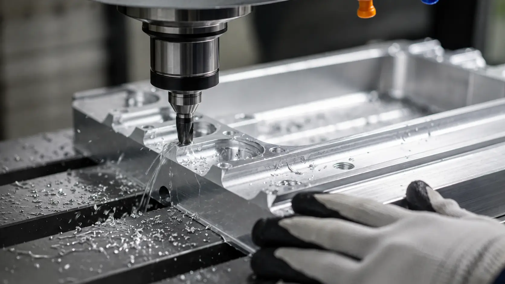
A simple bracket may follow a straightforward route. A housing with deep pockets, thin walls, precision bores, and features on several faces may need a very different approach. Tool access, workholding, datum relationships, cutting forces, and the order of machining can all change the final result.
What Is the CNC Machining Process?
The CNC machining process is the complete workflow used to manufacture a component with computer-controlled machine tools. It generally moves through five main stages: part definition, CAM programming, CNC machine setup, machining, and finishing and inspection.
CNC machining is a subtractive process. Cutting tools remove material from billet, plate, bar, extrusion, casting, or another starting form until the required geometry remains. Milling, turning, drilling, boring, reaming, and threading are individual operations that may be used within this broader process.
CNC Machining Process Step by Step
1. CAD Design and Part Requirements
The 3D CAD model defines the nominal geometry, while the engineering drawing communicates requirements such as tolerances, GD&T, datums, fits, threads, surface roughness, material, and finishing. These requirements often determine the machining strategy more than the visible shape of the part.
For example, holding the diameter of a bore may be straightforward, while maintaining its position relative to another feature machined from a different orientation can be more difficult. In that case, datum selection and setup planning become more important than the bore diameter alone. Deep pockets, thin walls, small internal radii, and hard-to-reach surfaces should also be identified before programming because they can affect tool selection and workholding.
2. CAM Programming
The CAD model defines where the finished surfaces should be. CAM programming determines how the cutting tools will create them. The programmer selects tools, builds toolpaths, sets cutting parameters, and determines the sequence of roughing and finishing operations.
A deep pocket illustrates why this stage requires more than selecting a cutter that can reach the bottom. Excessive tool overhang reduces rigidity, while higher cutter engagement in internal corners can increase cutting forces and cause deflection or chatter. A more stable strategy may use a larger tool for roughing, controlled engagement around corners, and a separate finishing pass with more uniform stock.
3. CNC Machine Setup
The CNC program contains coordinates, but those coordinates must be connected to the actual workpiece. The operator secures the material with a vise, chuck, soft jaws, clamps, or another fixture, then establishes the work coordinate system and verifies the cutting tools and offsets.
Good workholding is not simply about clamping the part as tightly as possible. The fixture should locate the workpiece consistently before the clamping force holds it in position. Thin or flexible parts can distort under excessive clamping pressure and move again when released. A part may therefore measure correctly inside the fixture and fall outside tolerance in its free state.
Datum control also becomes important when the component needs several setups. Features produced after the part is rotated or flipped must remain correctly related to geometry machined earlier. Reducing setup count can help, but only when the available tool access and workholding remain stable.
4. CNC Machining
This is where the programmed toolpaths become actual material removal. Roughing normally removes most of the excess stock, while finishing brings critical dimensions and surfaces to their final condition.
Roughing and Finishing
Roughing and finishing have different objectives. Roughing prioritizes stable material removal, while finishing controls the final cut. Leaving a small amount of stock on important surfaces gives the finishing tool a more predictable amount of material to remove.
The sequence becomes especially important on thin-wall or heavily machined parts. A solid billet may remain rigid early in the cycle but lose stiffness as pockets and walls take shape. If a critical wall is finished too early, later material removal can allow the part to move and change that finished feature. For some components, roughing the major geometry first and finishing critical surfaces later produces a more stable result.
Residual stress in plate, extrusion, or other stock can create similar movement. When large amounts of material must be removed, machining opposing areas or leaving finishing allowance can provide an opportunity to correct movement before the final dimensions are produced.
Additional Setups and Tool Access
Not every feature can be reached from one orientation. A housing may require machining from the top, bottom, and sides, while a turned component may still need milled flats, slots, or cross holes.
Fewer setups can reduce datum-transfer error, but one setup is not automatically more accurate. If keeping the part in one orientation requires a long, flexible tool, a controlled second setup with a shorter cutter may give a better result. The real decision is a balance between datum continuity and cutting stability.
Hole-making also depends on the final requirement. Drilling may be enough for a clearance hole, while a controlled bore may require boring or reaming. Threads may use tapping, thread milling, or turning depending on the geometry and required control.
5. Finishing and Inspection
Some parts leave the machine in the as-machined condition. Others require anodizing, bead blasting, passivation, plating, powder coating, painting, polishing, or another surface treatment. These requirements should be known before machining ends because coatings can affect dimensions. Precision bores, threads, and mating surfaces may require masking or allowance for coating thickness.
Inspection verifies whether the finished part actually meets the drawing. Calipers, micrometers, gauges, height measurement equipment, optical systems, and CMMs may all be used depending on the feature. The inspection method should follow the requirement being controlled rather than simply using the most sophisticated equipment available.
Timing also matters. A machinist may measure a critical bore before the final pass and adjust the tool offset while material is still available for correction. Flexible parts may need final measurement after unclamping because the free-state geometry is more relevant than the condition imposed by the fixture.
Main CNC Machining Operations
Different machining operations may appear within the same CNC process. The part geometry and feature relationships determine which methods make sense.
CNC Milling
CNC milling uses rotating cutting tools to machine housings, brackets, plates, pockets, slots, holes, and other prismatic features. Standard 3-axis equipment can produce a large range of components, while 4-axis and 5-axis machining can provide access to additional faces and angled geometry.
The benefit of additional axes is often reduced repositioning rather than accuracy by itself. If a part can be held rigidly and machined efficiently on a 3-axis machine, moving it to 5-axis equipment does not automatically improve the result.
CNC Turning
CNC turning rotates the workpiece while the cutting tool removes material. It is well suited to shafts, bushings, pins, sleeves, rings, connectors, and other components based around a central axis.
A turned part may still require milling for flats, keyways, cross holes, or slots. Depending on the geometry and equipment, these features may be produced with driven tooling on a turn-mill machine or during a separate milling setup.
CNC Drilling and Hole Machining
A hole can require different operations depending on what the drawing asks it to do. Standard drilling may be sufficient for a clearance hole, while a precision bore can require drilling followed by boring or reaming.
Diameter is only one consideration. Position, straightness, orientation, thread requirements, and the relationship to surrounding features may have a greater effect on the machining and inspection strategy.
Why the CNC Machining Process Varies Between Parts
Consider two parts made from Aluminum 6061.
The first is a thick mounting plate with shallow pockets and through holes. Standard workholding can support it well, short tools can reach the geometry, and the component remains relatively rigid throughout machining. The process may be simple.
The second is a thin-wall housing with a deep cavity, precision bores on opposite faces, side holes, and an anodized finish. The machining team may need to preserve support during roughing, use longer tools for deep features, control datum transfer between setups, delay critical finishing until major stock removal is complete, and account for coating on functional surfaces.
Both parts use the same material, but the manufacturing difficulty is completely different. Geometry, tolerance relationships, stiffness, tool access, setup requirements, surface treatment, and production quantity determine the process more reliably than material or overall part size alone.
What Should a CNC Machining RFQ Include?
A CNC machining RFQ should provide enough information for the supplier to understand both the geometry and the manufacturing requirements.
3D CAD Model: Provide a STEP, STP, IGES, Parasolid, or another usable 3D file for geometry review and CAM programming.
2D Engineering Drawing: Include critical dimensions, tolerances, GD&T, datums, fits, threads, surface roughness, and requirements that cannot be communicated reliably through nominal CAD geometry.
Material Specification: State the required material, alloy grade, and any relevant heat-treatment or material condition.
Quantity: Provide the prototype or production quantity. Quantity can affect workholding, fixture strategy, and the level of process optimization that makes economic sense.
Surface Finish Requirements: Specify whether the part remains as-machined or requires anodizing, bead blasting, passivation, plating, powder coating, painting, or another treatment.
Inspection and Documentation Requirements: Identify critical features, inspection reports, CMM requirements, material certificates, or other documentation required with the order.
For a simple component, a 3D model, material, quantity, and finish may support an initial quotation. A controlled drawing becomes more important when the design includes tight fits, GD&T, critical interfaces, or specific inspection requirements.
ZH Precision reviews CAD files and engineering drawings for prototype and production CNC machining projects. Providing complete project information before quotation helps confirm the machining method, setup requirements, tolerances, finishing, and inspection needs before production begins.
Conclusion
The CNC machining process is more than a sequence of automated cutting operations. The manufacturing team must decide how to locate the part, maintain tool rigidity, control the way the workpiece changes as material is removed, preserve critical feature relationships between setups, and verify the finished condition.
Good process planning is therefore about identifying the dominant risk in each part. For one component, that may be deep tool access. For another, it may be clamping distortion, datum transfer, or loss of stiffness during roughing. The most effective process controls those issues before they become dimensional problems on the finished part.
FAQ
Yes. A bore or other feature can meet its individual size tolerance while failing the required position, orientation, or relationship to another feature. The machining and inspection strategy must therefore consider the datum structure as well as individual dimensions.
Clamping force can temporarily distort thin or flexible components. The part may measure correctly while held in the fixture and then move after the clamps are released. Changing support, clamping force, machining sequence, or free-state inspection may be necessary.
Long tool overhang reduces rigidity. Cutting forces can push the cutter away from the programmed path, particularly near deeper sections or areas of higher tool engagement. This can produce wall taper, chatter, or local dimensional variation.
Roughing removes most of the material efficiently, while finishing produces the final dimensions under more controlled cutting conditions. Separating the two also allows much of the change in part stiffness and stress balance to occur before the machinist finishes the critical surfaces.




