

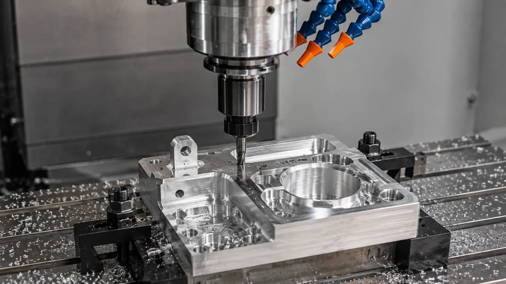
For a part whose geometry fits within three axes, it’s usually the lowest-cost way to produce it, provided the required features remain accessible without too many additional setups.
This guide covers how 3-axis machining works, how parts are held and cut, what the process can and can’t produce, how it compares to 4-axis and 5-axis machining, and how to design a part so it stays within 3-axis territory and avoids unnecessary setup costs.
What Is 3-Axis CNC Machining?
3-axis CNC machining moves a rotating cutting tool along three linear axes, X, Y, and Z, while the workpiece stays fixed in a vise or fixture during each setup. X and Y position the tool across the part’s surface; Z controls cutting depth.
This is one of the simplest and most common CNC configurations. Nearly every CNC milling machine is at minimum capable of 3-axis movement. Many parts that could technically use more axes are still produced on three because the added axes aren’t always necessary.
Unlike 4-axis and 5-axis machining, the tool orientation remains fixed during a conventional 3-axis operation. The machine can still produce pockets, contours, holes, and 3D surfaces through coordinated X, Y, and Z movement, but the cutter has to reach those features from the current setup orientation.
For a broader introduction to the process, see What Is CNC Machining?
How 3-Axis CNC Machining Works
The workpiece is clamped in a vise, fixture, or on a sub-plate and stays in that fixed position for the duration of the operation. The spindle carries the cutting tool and moves it along the programmed X, Y, and Z path to remove material in successive passes.
Because the tool orientation remains fixed in a conventional 3-axis setup, every feature machined during that operation has to be reachable from the current cutting direction. A feature on the side or bottom of the part, such as a hole through a side wall or a pocket on the underside, may require the part to be flipped or rotated into a new setup and referenced to the required datums again.
Programming for 3-axis work is comparatively simple because the toolpath only has to account for tool position in three dimensions rather than continuously controlling tool orientation as well. This generally keeps CAM programming and machine setup simpler than 4-axis or 5-axis work.
Workholding Strategies for 3-Axis Machining
Workholding, how the part is secured during machining, has to resist cutting forces in X, Y, and Z without deflecting the part or blocking tool access to the features being cut.
The method chosen affects both cycle time and achievable tolerance because any movement or distortion in the workpiece can affect the finished dimensions.
Vise Workholding
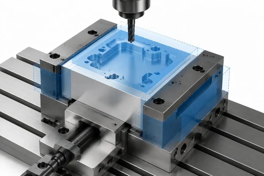
A vise is the default for many prismatic parts with parallel reference faces. It’s fast to set up and re-set for repeat orders, but the jaws occupy space along two sides of the part.
This can block access to features near the clamped edges and has to be considered during setup and toolpath planning.
Vacuum Fixtures
A vacuum fixture holds the part by suction across a flat face, leaving the outer edges open for machining.
This suits thin plates and parts where vise jaws would otherwise interfere with a feature. However, it depends on a sufficiently flat, non-porous mounting surface to maintain vacuum.
Clamping force is also lower than with many mechanical workholding methods, which can limit how aggressively the part is machined.
Custom Fixtures and Sub-Plates
A custom fixture, often a machined sub-plate with locating pins and clamps matched to the part’s geometry, can be worth the tooling investment when a part runs in enough volume to amortize it.
It may also be useful when the geometry cannot be held reliably in a standard vise or vacuum setup.
For a one-off prototype, fixture cost may not pay back. For repeat production, a well-designed fixture can reduce loading time and improve positioning consistency.
Workholding for Thin-Walled Parts
Thin-walled or easily distorted parts need a workholding strategy that spreads clamping force rather than concentrating it.
A vise applying excessive pressure across a thin section can distort the geometry before the first cut is made.
This can be managed with lower clamping pressure, additional support under the workpiece, soft jaws shaped to the geometry, or a vacuum fixture that distributes holding force across a larger surface.
What Can and Can’t Be Machined on 3 Axes
What 3-Axis Machining Can Produce
3-axis CNC milling can produce flat faces, pockets, slots, drilled and tapped holes, and contoured surfaces as long as the cutting tool can reach the required geometry from the current setup orientation.
A plate, a bracket with accessible features, or a housing with one open face are all common examples of parts that can be machined efficiently on three axes.
Contoured geometry does not automatically require a 5-axis machine. A 3-axis machine can produce many 3D surfaces by moving X, Y, and Z simultaneously while keeping the cutter orientation fixed.
What Falls Outside a Single 3-Axis Setup
Features located on other faces may fall outside what a single setup can reach:
- A hole through a side wall
- A boss on the underside
- A slot cut into an angled or inaccessible face
Producing these features may require a second setup. The operator flips or rotates the part and re-establishes its position from the required datum surfaces.
Rotary axes can reduce this manual repositioning, but a side feature does not automatically justify 4-axis or 5-axis machining. Whether another 3-axis setup or a higher-axis process makes more sense depends on feature access, tolerance relationships, quantity, workholding, and setup cost.
Undercuts also require closer review.
A standard end mill approaching from a fixed direction cannot reach behind every overhang. However, some undercuts can still be machined on 3-axis equipment with a T-slot cutter, lollipop cutter, dovetail cutter, keyseat cutter, or another specialized tool.
Tool access has to be checked for the complete cutting assembly. The cutter may reach the surface while the tool shank or holder collides with surrounding geometry.
Deep, narrow pockets create a different limitation. Long tool reach reduces rigidity and can increase deflection, vibration, and surface finish problems even when the geometry is technically accessible.
Toolpath Strategy: Roughing, Semi-Finishing, and Finishing
Roughing, Semi-Finishing, and Finishing Passes
Most 3-axis programs run in stages rather than cutting a feature to final size in one pass.
Roughing removes the bulk of the material quickly, using a larger stepover and stepdown while leaving material for later passes.
Semi-finishing brings the part closer to final dimensions with a lighter cut and can leave a more consistent amount of stock for finishing.
Finishing then uses lighter cutting conditions and an appropriate toolpath to achieve the required dimensions and surface condition.
Climb Milling vs Conventional Milling
Climb milling, where the cutter rotates in the same general direction as the feed at the cutting point, is commonly preferred on modern CNC machining centers because it often provides favorable cutting conditions and good surface finish.
Conventional milling still has applications depending on the material, workholding, cutter engagement, machine condition, and specific toolpath.
The choice should follow the machining conditions rather than assuming one method is always correct.
Chip Evacuation in Deep Features
Chip evacuation becomes a real constraint once a pocket gets deep relative to its width.
Chips that cannot escape the cutting area may be recut against the tool and finished surface. This increases heat and tool wear and can damage surface finish.
Through-tool coolant, external coolant, air blast, appropriate flute geometry, and toolpaths that provide enough space for chip evacuation can all help manage deeper features. Periodic chip-clearing retracts may also be useful depending on the operation.
3-Axis vs 4-Axis vs 5-Axis: When 3-Axis Is the Right Choice
| Factor | 3-Axis | 4-Axis | 5-Axis |
|---|---|---|---|
| Motion | X, Y, Z linear | Adds one rotary axis | Adds two rotary axes |
| Feature access | Fixed tool orientation per setup | Reaches features around one rotary axis with less manual repositioning | Provides greater access to multi-face and angled geometry |
| Programming complexity | Lowest | Moderate | Highest |
| Typical machine rate | Lowest | Moderate | Highest |
| Best fit | Features accessible from one or a few straightforward orientations | Features distributed around a rotational axis | Complex multi-face, angled, or contoured geometry |
3-axis machining isn’t a fallback used only when more advanced equipment isn’t available.
For a part whose features all sit on one accessible face, or on faces reachable with one or two straightforward setups, it’s usually the cheaper and faster option. Adding axes that the geometry does not require can add programming complexity and machine cost without providing a meaningful manufacturing advantage.
The decision comes down largely to feature count, orientation, and relationships between features rather than part size or apparent complexity.
A large, visually complex part with accessible features may still machine efficiently on three axes. A small, simple-looking part with a tightly controlled hole on another face may require a second setup or benefit from rotary positioning.
A useful first check is therefore not simply the physical size of the part, but how many machining orientations its functional features require.
Tolerances and Surface Finish Achievable on 3-Axis Machining
Achievable Tolerances
3-axis machining can support both general machining tolerances and tighter control on selected functional features.
General tolerances around ±0.05 mm to ±0.13 mm are common for many conventional CNC parts, but this range should not be treated as a universal capability of every 3-axis machine.
Actual achievable tolerance depends on factors such as:
- part geometry
- feature size
- material
- workholding
- cutter condition
- machine capability
- setup count
- thermal stability
- inspection method
Tighter tolerances may be achievable on selected features through suitable tooling, finishing passes, controlled setups, and appropriate inspection.
For a deeper discussion of these factors, see CNC Machining Tolerances.
Surface Finish
As-machined surfaces may commonly fall around 0.8 to 3.2 μm Ra on suitable features, but this is not a fixed 3-axis machining range.
Surface roughness depends on tool selection, tool condition, feed rate, stepover, material, cutting direction, and the type of surface being machined.
Ra, or roughness average, is one commonly used parameter for specifying surface texture. ASME B46.1 is a widely used reference for surface texture specification and measurement.
Contoured surfaces machined with a ball-nose cutter can show visible toolpath scallops between passes. A finer stepover can reduce those scallops, but it also increases toolpath length and machining time.
Positional Accuracy Across Setups
Positional accuracy between features machined in the same setup is generally easier to control because the features share the same established coordinate system.
Accuracy between features split across two setups depends on how precisely the second setup re-establishes the required datum references.
This is one reason minimizing setup count matters for tolerance, not just cost.
Where a drawing uses positional tolerances under a GD&T standard such as ASME Y14.5, the datum scheme and workholding strategy become especially important. Additional setups introduce another opportunity for datum-transfer variation, so tightly related features may require more careful fixturing, probing, and inspection.
Design Guidelines (DFM) for 3-Axis Machining
Keep Features on One Face
This is one of the highest-leverage design decisions available.
Placing related features on as few faces as practical, ideally one where the design allows it, can reduce the number of times the part needs flipping or re-fixturing.
This is particularly valuable when features have a tight positional relationship to one another.
Match Internal Corners to Practical Tooling
A 3-axis end mill naturally leaves a radius in internal corners.
A pocket specified with a very small internal corner radius forces the use of a smaller-diameter cutter. Smaller tools are generally less rigid and may require slower cutting conditions or additional passes.
Larger internal radii allow the machinist to use larger, more rigid cutters.
For deeper pockets, the corner radius should be considered together with pocket depth and available tool diameter rather than treated as an isolated dimension.
Where a true sharp internal corner is functionally required, a secondary process such as EDM may be necessary.
Watch Pocket Depth-to-Width Ratio
Deep, narrow pockets increase tool reach and reduce cutter rigidity.
As a rough starting guideline, keeping effective cutting depth within approximately four to five tool diameters is practical for many conventional milling operations.
This is not a fixed machining limit.
Deeper pockets are possible, but they may require longer tooling, slower cutting parameters, specialized toolpaths, and more attention to vibration and chip evacuation.
Check Tool and Holder Access
Tool accessibility should be evaluated beyond the cutting edge itself.
A cutter may technically reach the required surface while the tool shank, collet, or holder collides with surrounding walls, bosses, or other geometry.
This becomes particularly important around deep cavities, tall walls, narrow openings, recessed features, and undercuts.
Where possible, providing more clearance around deep or restricted features gives the machinist more freedom to use shorter and more rigid tooling.
For a broader explanation of these design considerations, see the CNC Machining DFM Guide.
Materials Commonly Machined on 3-Axis Equipment
| Material | Machinability | Typical Use |
|---|---|---|
| Aluminum 6061 | High | General structural parts, enclosures |
| Aluminum 7075 | Moderate-high | High-strength structural parts |
| Brass C360 | High | Fittings, electrical components |
| Stainless Steel 304/316 | Moderate | Corrosion-resistant parts |
| Carbon Steel 1045 | Moderate-high | Structural and mechanical components |
| Engineering Plastics | High | Lightweight or non-conductive parts |
3-axis machines can handle the same broad range of metals and engineering plastics used in other CNC milling operations.
Material choice affects feed rate, cutter selection, tool wear, workholding, surface finish, and cycle time. It does not by itself determine whether a part needs more axes.
Axis selection is driven primarily by geometry and feature access, while setup count, tolerance relationships, workholding, quantity, and machining economics influence the final process choice.
Cost Considerations: Why 3-Axis Is Often the Lower-Cost Option
3-axis machine rates are generally lower than 4-axis or 5-axis rates because the machines are less complex and programming requirements are usually simpler.
For a part whose geometry fits efficiently within three axes, this often makes 3-axis machining the lower-cost approach without sacrificing the capability the part actually needs.
Cost rises when geometry forces multiple setups.
Each additional setup can add:
- fixturing time
- part handling
- datum re-referencing
- alignment or probing
- in-process inspection
These are costs that a single 4-axis or 5-axis setup may sometimes avoid.
Whether 3-axis machining with additional setups or a higher-axis machine with fewer setups costs less depends on the complete manufacturing route. Setup count, tolerance relationships, quantity, machine rate, and fixture requirements all need to be considered together.
At low order quantities, the fixed cost of an additional setup is spread across relatively few parts, which can increase the per-part impact.
At higher quantities, fixture design and repeatable workholding can reduce loading and setup time, changing the economics again.
ZH Precision evaluates both routes when the setup count is close rather than automatically assigning a higher-axis process. CNC milling services include 3-axis, 4-axis, and 5-axis machining based on the geometry, tolerance requirements, and production needs of the part.
Conclusion
3-axis machining is the default starting point for many CNC milled parts, not a limited fallback option.
It handles parts whose major features remain accessible from a fixed tool orientation or through a small number of straightforward setups, often at a lower machine rate and with simpler programming than higher-axis equipment.
The design decision that matters most is keeping critical features accessible from as few orientations as practical.
Tool access, workholding, internal radii, pocket depth, setup count, and tolerance relationships all influence whether a part stays efficient on three axes.
When additional setups begin to add significant fixturing, datum transfer, inspection, or machining time, comparing the complete 3-axis route with 4-axis or 5-axis machining is more useful than choosing a process based on axis count alone.




