

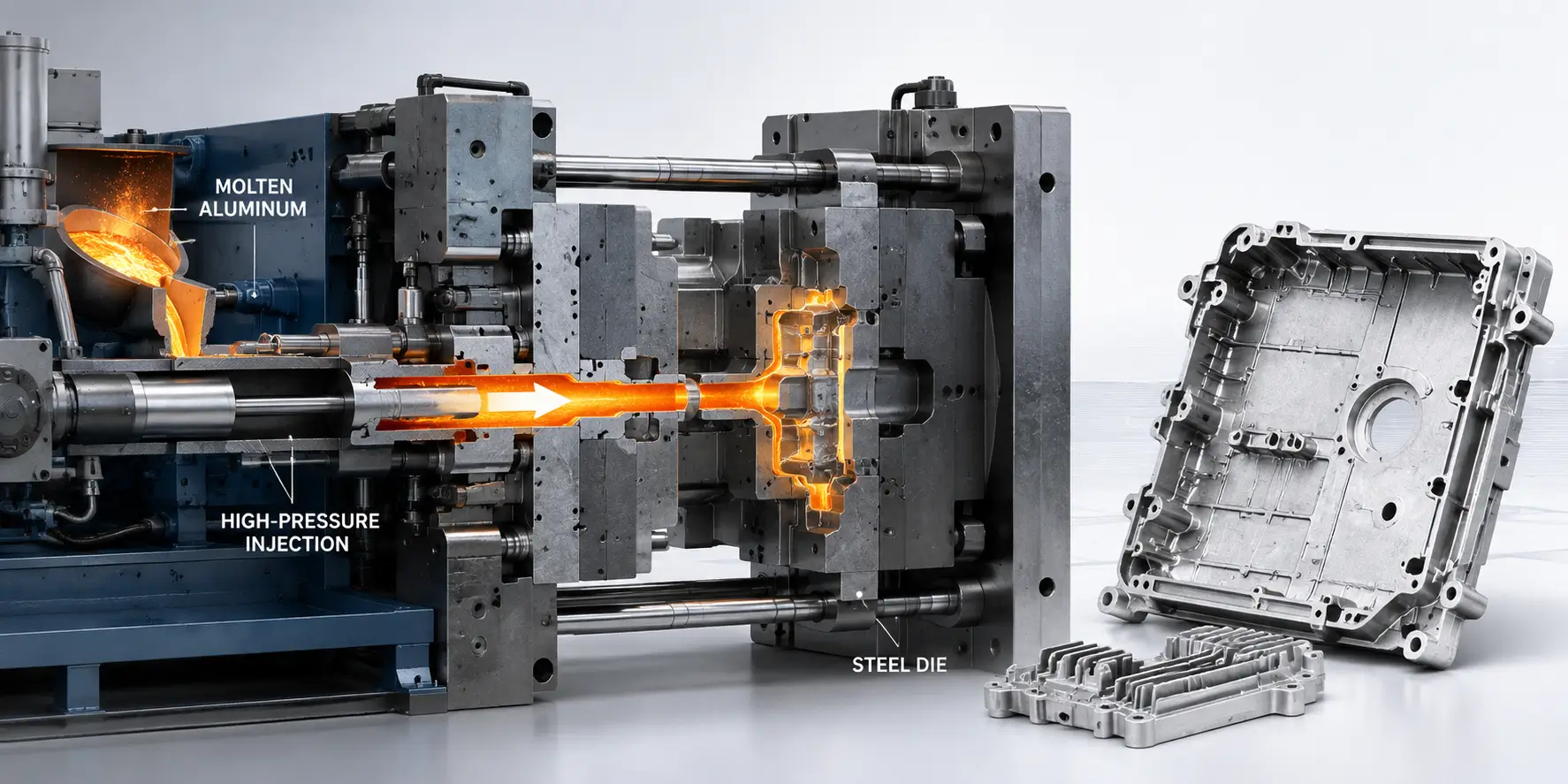
This guide covers how HPDC actually works: the hot chamber and cold chamber processes, the four stages of a casting cycle, the aluminum, zinc, and magnesium alloys used in production, the design rules that keep a die castable, and the tolerances and defects an engineer should plan around before a part goes to tooling.
What Is High Pressure Die Casting (HPDC)?
High pressure die casting is a metal casting process in which molten metal is injected into a permanent steel mold, or die, under high pressure and held there until the part solidifies. Unlike sand casting or investment casting, which use expendable molds, the die in HPDC is reusable and typically machined from hardened tool steel, since it has to withstand a high number of cycles at high pressure and temperature over its service life.
The process is built for volume. A single die can produce tens of thousands to hundreds of thousands of parts before significant rework is required, although actual die life depends on the alloy, casting temperature, part geometry, thermal loading, and tool maintenance. Cycle times for smaller parts can also run under a minute. That combination of speed and repeatability is why HPDC is widely used for automotive structural components, engine and powertrain parts, electronic housings, and other components where the tooling cost can be justified by high production quantities.
HPDC is generally limited to non-ferrous alloys with lower melting points, primarily aluminum, zinc, and magnesium. Casting steel or other high-melting-point metals is not primarily a pressure limitation but a thermal and tooling problem. Their casting temperatures would subject reusable steel dies to severe thermal fatigue, erosion, and other forms of damage that make conventional HPDC impractical.
Hot Chamber vs. Cold Chamber Die Casting
HPDC splits into two distinct machine types, and the choice between them is driven largely by the alloy being cast.
Hot Chamber Die Casting Process
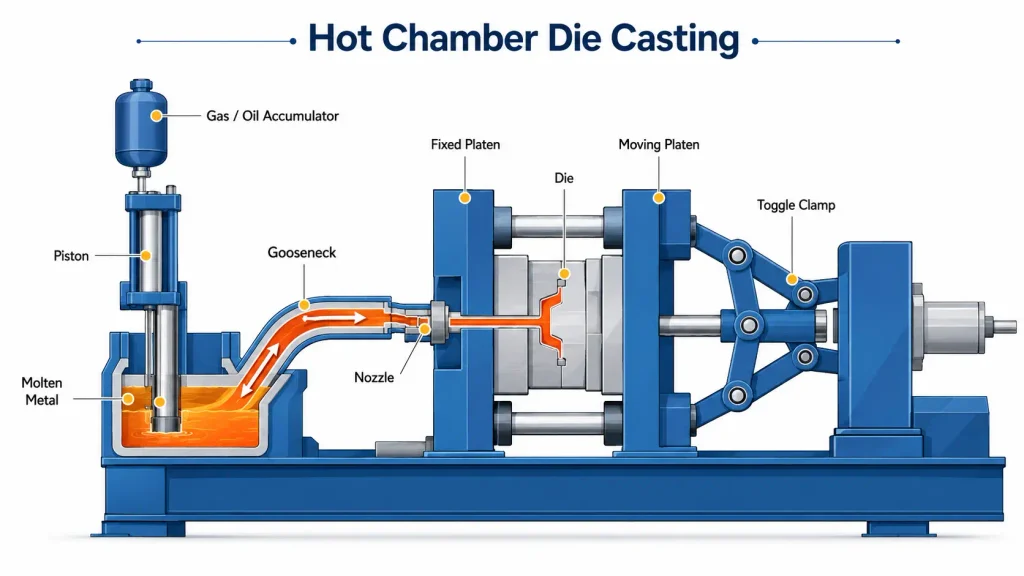
In hot chamber die casting, the injection mechanism sits in or is directly connected to a reservoir of molten metal. A gooseneck channel feeds metal from the melt, and a hydraulic or mechanical plunger forces it through the injection system into the die cavity.
Because the metal does not have to be transferred into a separate shot sleeve for every cycle, hot chamber machines can operate quickly and efficiently at high volume.
The limitation is the continuous contact between molten metal and the injection components. Hot chamber machines are therefore mainly used with lower-melting-point alloys that do not rapidly attack the injection system. Zinc and some magnesium alloys are the primary candidates.
Aluminum is generally not run in conventional hot chamber machines because molten aluminum reacts aggressively with ferrous components in the injection system at casting temperature.
Cold Chamber Die Casting Process
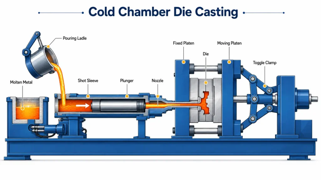
In cold chamber die casting, molten metal is ladled or automatically dosed into a separate shot sleeve for each cycle rather than remaining in continuous contact with the injection system. A plunger then drives the metal from the shot sleeve through the runner and gate system into the die.
This adds a transfer step compared with hot chamber casting, so cycle times are generally longer. The advantage is that the injection hardware is not continuously immersed in the molten alloy.
That isolation makes cold chamber machines suitable for aluminum and other alloys that are not compatible with conventional hot chamber equipment. Nearly all aluminum HPDC, including automotive structural castings, powertrain housings, motor housings, and many EV components, is produced using cold chamber machines.
High Pressure Die Casting Process Steps
Regardless of whether a hot chamber or cold chamber machine is used, the high pressure die casting process follows four core stages. Each stage introduces its own process variables, and many defects found in a finished casting can be traced back to what happened during one of these stages.
Die Preparation and Clamping
Before each shot, the die is prepared for the next casting cycle. Depending on the process, lubricant or release agent may be applied to the cavity surface to assist ejection, reduce sticking, and help manage die temperature from cycle to cycle.
The two die halves are then closed and clamped with enough force to resist the cavity pressure generated during injection.
Required clamping force depends largely on the projected area of the casting and the pressure acting inside the die. Production HPDC machines range from relatively small presses to machines with several thousand tons of clamping force for large structural castings.
If the clamping system cannot resist the forces created during the shot, the die can open slightly along the parting line and allow molten metal to escape, producing flash.
Injection and Fill
Molten metal is driven into the die cavity at high speed, with the final cavity fill often occurring in only a fraction of a second.
In cold chamber HPDC, the plunger movement is normally divided into different velocity phases. The first phase moves the metal through the shot sleeve in a controlled manner to limit excessive air entrainment. Once the metal reaches the appropriate position, the plunger accelerates and drives it rapidly through the gate into the cavity.
The cavity needs to fill before thin sections or advancing flow fronts cool enough to solidify prematurely. At the same time, excessive turbulence can trap air inside the casting.
This is why runners, gates, vents, overflow wells, and, where required, vacuum systems need to be designed as one flow system. They control how metal enters the cavity, where flow fronts meet, and how displaced air escapes before it becomes trapped inside the part.
Intensification and Solidification
Once the cavity is filled, pressure is maintained or increased during the early stage of solidification.
This intensification phase helps maintain pressure on the metal and can compensate for some solidification shrinkage while pressure can still be transmitted through the gate. Once the gate has frozen, however, isolated regions can no longer be fed effectively.
Cooling channels built into the die remove heat during this stage. Their position and flow rate, together with wall thickness, die temperature, alloy temperature, and cycle time, affect how evenly different regions of the part solidify.
Areas that remain hot significantly longer than surrounding sections are more likely to develop shrinkage porosity or dimensional distortion.
Ejection and Trimming
Once the casting has solidified enough to retain its shape, the die opens and ejector pins push the part free.
Draft angles on surfaces parallel to the die-opening direction help the casting release without excessive friction against the tool. Insufficient draft can increase ejection force and contribute to sticking, surface damage, distortion, or accelerated die wear.
The part that comes out of the die is not finished yet. It is normally still attached to gates, runners, the biscuit, and overflow material. These are removed by trimming or secondary cutting.
The casting may then move through operations such as deburring, shot blasting, surface finishing, leak testing, heat treatment where appropriate, or CNC machining of features that require tighter dimensional control than the casting process alone can provide.
Materials for High Pressure Die Casting
Alloy selection in HPDC is narrower than in CNC machining because the process itself limits the usable materials to metals that can be cast efficiently at temperatures compatible with reusable steel tooling.
Material choice affects more than the mechanical properties of the finished part. It also influences fluidity, casting temperature, shrinkage, die life, corrosion resistance, surface finishing, and secondary machining.
Aluminum Alloys for Die Casting
Aluminum is one of the most widely used HPDC materials for structural and load-bearing components because it combines low density, useful mechanical strength, corrosion resistance, and the ability to form complex thin-walled geometry.
Common aluminum die casting grades include A380, A383, A360, A413, and other regional alloy designations. Each alloy balances castability, strength, corrosion resistance, pressure tightness, and machinability differently.
A380 is widely used as a general-purpose aluminum die casting alloy because it provides a practical balance between mechanical performance, castability, and cost. Other grades may be selected where improved corrosion resistance, pressure tightness, fluidity, or specific mechanical properties are more important.
Aluminum HPDC uses cold chamber equipment and is commonly found in automotive structural components, engine and gearbox housings, motor housings, electronic enclosures, industrial housings, and EV powertrain components.
Zinc Alloys for Die Casting
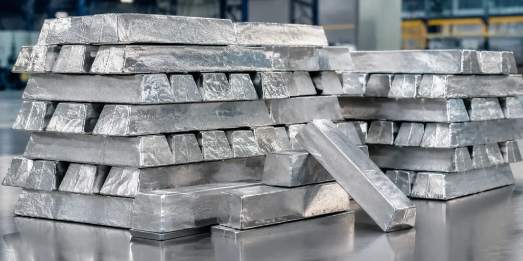
Zinc alloys offer excellent castability, good ductility and impact resistance, and the ability to reproduce fine details and thin sections.
Their relatively low melting temperature makes them particularly suitable for hot chamber casting. It also reduces the thermal load placed on the die compared with higher-temperature aluminum casting, which can contribute to longer tool life under suitable production conditions.
Zinc is commonly used for small precision components, connectors, mechanisms, hardware, housings, and decorative parts where dimensional detail, surface quality, and toughness are more important than achieving the lowest possible weight.
Magnesium Alloys for Die Casting
Magnesium is the lightest structural metal commonly processed by die casting and is selected where reducing component weight is a major design priority.
Typical applications include lightweight housings, frames, electronic structures, automotive components, and other products where mass reduction is important.
Depending on the alloy, machine configuration, and part requirements, magnesium can be processed using either hot chamber or cold chamber equipment.
Its reactivity also requires more controlled melting, handling, and downstream machining practices than aluminum or zinc, which needs to be considered when planning the complete manufacturing process.
Design Guidelines for High Pressure Die Casting (DFM)
A part that can be CNC machined does not automatically make a good die casting.
Die casting design has to account for how molten metal fills a closed cavity, where air escapes, how different sections cool, how the die opens, and how the solidified casting is removed.
These factors should be addressed before tooling begins because changes become considerably more expensive once the die has been manufactured.
Wall Thickness and Draft Angles
Wall thickness in HPDC has a narrower practical range than in machining.
Walls that are too thin can create short shots because the metal begins to solidify before the cavity is completely filled. Walls that are unnecessarily thick cool more slowly and can increase the risk of shrinkage porosity, sink-related surface effects, and dimensional distortion.
Uniform wall thickness is therefore generally preferable to abrupt changes between thick and thin sections.
The appropriate wall thickness depends on alloy, flow length, part size, machine capability, gate location, and required mechanical performance. A generic minimum thickness should not be applied to every casting without considering these factors.
Draft angles are required on surfaces that must release from the die. The amount of draft depends on wall height, surface texture, alloy, geometry, and whether the feature is internal or external.
Deeper surfaces and textured cavities generally need more draft than shallow, smooth surfaces.
Ribs, Bosses, and Undercuts
Ribs are commonly used to increase stiffness without increasing the entire wall thickness.
A thick solid section cools more slowly and can create a local thermal hot spot. A thinner wall supported by ribs can often provide the required stiffness while reducing material usage and improving solidification behavior.
Rib intersections should still be designed carefully because adding too much local material where the rib meets the wall can create another heavy section.
Bosses for fasteners or locating features follow similar principles. Large solid bosses can become local hot spots, so coring and rib support may be used where appropriate to control section thickness.
Undercuts should be minimized where possible because they often require moving slides, cores, or other die-side actions.
These features are completely normal in HPDC, but each moving component adds tooling complexity, wear surfaces, possible flash locations, maintenance requirements, and cost.
If an undercut can be redesigned as a straight-pull feature without compromising function, that option is usually worth considering before the tool design is finalized.
Parting Line and Gate Location
The parting line and gate location are usually established early in tooling development because both affect many downstream decisions.
The parting line influences how the tool opens, where flash can occur, how the casting is ejected, which dimensions cross separate tool components, and where a visible parting-line witness may remain on the finished part.
Gate location influences how molten metal enters and travels through the cavity.
Good gate design needs to consider wall thickness, flow distance, metal velocity, flow-front convergence, venting, overflow position, local solidification, and trim accessibility together.
The goal is not simply to put the gate at the thickest section. It is to develop a filling pattern that can complete the cavity without excessive turbulence, premature freezing, or trapped air.
Achievable Tolerances in High Pressure Die Casting
HPDC produces tighter and more repeatable as-cast dimensions than many conventional casting processes, but it still cannot provide CNC-machining-level control on every feature.
Where a dimension is located relative to the die structure has a major influence on its achievable tolerance.
A feature formed entirely within one die half can generally be controlled more consistently than a dimension that crosses the parting line. Features produced by moving slides, long cores, or inserts introduce additional sources of variation because their final position depends on mechanical interfaces inside the tooling.
Tool wear also affects dimensional capability over time. Parting surfaces, slides, cores, ejector components, and cavity surfaces experience repeated thermal and mechanical cycling during production.
For features that require tighter control than the casting can reliably provide, such as bearing bores, sealing surfaces, precision locating holes, shaft interfaces, or critical mounting surfaces, the common approach is to cast them near net shape and machine them afterward.
This is usually more economical than applying unnecessarily tight tolerances across the entire casting.
A drawing should therefore distinguish between dimensions that can remain as-cast and features that genuinely need secondary machining.
If a critical tolerance is difficult to evaluate from the drawing alone, ZH Precision can review the feature before tooling as part of its die casting services to determine whether it is more practical to control it in the die or reserve material for secondary CNC machining.
Common High Pressure Die Casting Defects and Causes
Most high pressure die casting defects can be traced back to how the metal fills, how air escapes, and how the casting solidifies.
Understanding the mechanism behind a defect is important because two defects that look similar may require completely different corrective actions.
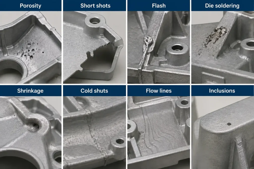
Porosity
Porosity is one of the most common defect categories in HPDC and generally falls into two main types: gas porosity and shrinkage porosity.
Gas porosity forms when air or other gases become trapped during the high-speed filling process instead of escaping through vents, overflow systems, or vacuum channels.
Shrinkage porosity develops when a section contracts during solidification without enough available liquid metal to compensate for the volume change.
The distinction matters because the two defects should not be solved in the same way.
Gas porosity usually requires review of the shot profile, filling pattern, venting, vacuum, gating, and air entrainment.
Shrinkage porosity requires more attention to wall thickness, hot spots, cooling, solidification sequence, and whether pressure can remain effective in the region while the casting solidifies.
Short Shots
A short shot occurs when the cavity does not fill completely.
The metal may cool and begin to solidify before reaching the end of a thin section or a region far from the gate.
Potential causes include insufficient filling velocity, low metal temperature, low die temperature, excessive flow distance, restrictive gate geometry, or sections that are too thin for the required flow path.
Cold Shuts
Cold shuts are related to short shots but are not the same defect.
They occur when separate metal flow fronts meet after cooling enough that they fail to fuse completely.
The cavity may still appear full, but the meeting line can remain as a visible seam and may create a local mechanical weakness.
Flow pattern, gate position, metal temperature, die temperature, and fill time can all contribute.
Flash
Flash is excess metal that escapes through the parting line or around moving tooling components.
It can result from insufficient effective clamping force relative to cavity pressure, excessive injection conditions, tooling misalignment, or wear and damage along the die sealing surfaces.
A recurring flash problem should therefore not automatically be treated as a trimming issue. It can indicate a tooling or process-control problem upstream.
Die Soldering
Die soldering occurs when molten metal adheres to the die surface instead of releasing cleanly.
It is especially relevant in aluminum HPDC and is influenced by local die temperature, alloy chemistry, lubrication, cooling effectiveness, and die surface condition.
Local hot spots can make the problem more severe because the affected area remains at an elevated temperature for longer during repeated cycles.
Advantages and Limitations of High Pressure Die Casting
HPDC’s core advantage is its ability to produce complex, near-net-shape parts at high volume with good dimensional repeatability once the tooling and process are qualified.
The trade-off is the cost and commitment required before production begins.
| Advantages | Limitations |
|---|---|
| High dimensional repeatability once the die is qualified | High initial tooling cost |
| Fast cycle times support high production output | Tooling requires significant development before production |
| Complex near-net-shape geometry can be produced in one casting | Design changes become more expensive after the die is built |
| Thin walls and fine surface detail are achievable | Standard HPDC can contain internal gas porosity |
| Part consolidation can reduce separate components and assembly | Some precision features still require secondary machining |
| Good surface quality for many applications | Low quantities may not justify dedicated steel tooling |
| Low per-part casting time at high volume | Welding, heat treatment, or pressure-tight applications may require additional porosity control |
The economics of HPDC are therefore very different from CNC machining.
CNC machining requires relatively little dedicated tooling but adds machine time to every individual part. HPDC requires much more upfront tooling investment, but once the die is running, parts can be produced very quickly.
For prototypes or small production quantities, CNC machining or another lower-tooling-cost process may be more practical.
For stable designs produced in tens of thousands of parts or more, HPDC can become much more economical because the tooling investment is distributed across a larger production volume.
High Pressure Die Casting Applications
Automotive is one of the largest application areas for HPDC.
Typical applications include transmission housings, gearbox housings, engine components, motor housings, inverter housings, structural brackets, chassis components, and increasingly large aluminum structural castings used in electric vehicles.
Large-format HPDC has also increased interest in part consolidation. Multiple stamped, welded, or separately manufactured components can sometimes be redesigned as a smaller number of large castings, reducing component count and assembly operations.
Beyond automotive, HPDC is widely used in consumer electronics for enclosures, frames, and structural brackets, and in industrial equipment for motor housings, pump components, gearboxes, covers, and other repeated-production metal parts.
Communications equipment, appliances, electrical products, and selected medical devices can also use die cast components when production volume justifies dedicated tooling.
Aerospace uses HPDC more selectively, particularly for non-flight-critical components. Internal porosity and the qualification requirements associated with fatigue-critical aerospace structures make conventional HPDC less suitable for many primary structural applications.
Conclusion
High pressure die casting works best when a stable part design, complex geometry, and high production volume justify the investment in dedicated steel tooling. Its high-speed filling process can produce thin walls, detailed geometry, good surface quality, and repeatable near-net-shape parts in aluminum, zinc, and magnesium alloys.
The same high-speed process also makes early engineering decisions important. Wall thickness, draft, parting line location, gate design, venting, thermal balance, alloy selection, and tooling movement all influence whether the casting fills and solidifies consistently.
Tolerance strategy should be considered at the same stage. Not every dimension needs to be controlled directly by the die. Bearing bores, sealing surfaces, precision locating features, and other function-critical interfaces can often be cast near net shape and machined afterward, while the rest of the component remains as-cast.
For an engineer evaluating HPDC, the key question is therefore not simply whether a part can be cast. It is whether the geometry, tolerance requirements, alloy, tooling complexity, and expected production volume fit the process well enough to make HPDC the right manufacturing route.
FAQ
Hot chamber die casting keeps the injection system connected to the molten metal supply, allowing faster cycles and making it suitable for zinc and some magnesium alloys. Cold chamber die casting fills a separate shot sleeve for each cycle and is commonly used for aluminum and other higher-temperature alloys.
HPDC tolerance capability depends on part size, alloy, geometry, die condition, and feature location. Dimensions formed within one die half are generally easier to control, while features across parting lines or moving cores may need looser tolerances or secondary CNC machining.
Porosity usually comes from trapped gas or solidification shrinkage. Gas porosity is related to filling, venting, and air entrapment, while shrinkage porosity is more closely linked to wall thickness, hot spots, cooling, and solidification behavior.
Usually not. HPDC requires dedicated steel tooling, so CNC machining or other lower-tooling-cost processes are often more economical for prototypes and low quantities. HPDC becomes more attractive as production volume increases.
Yes. Secondary CNC machining is commonly used for bearing bores, sealing faces, locating holes, threads, and other critical features that need tighter control than the casting process alone can provide.




