

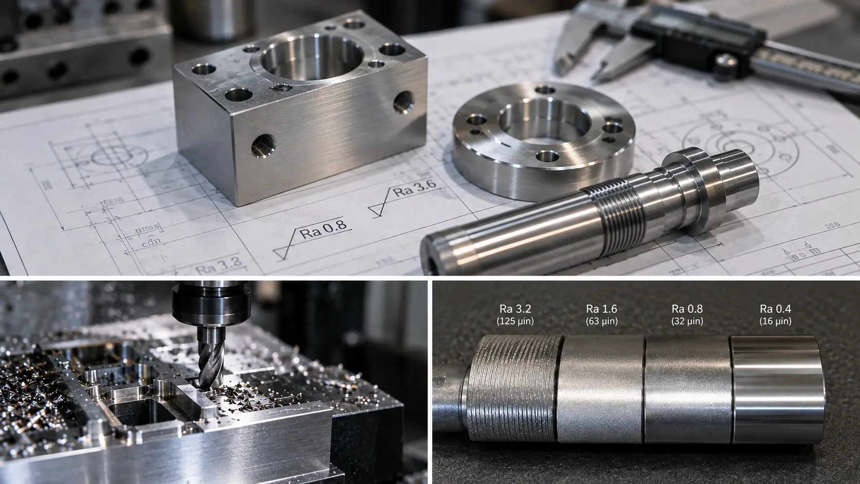
A surface finish chart is useful for translating common roughness values, but the number alone does not tell an engineer whether the requirement is appropriate. The same Ra value can be easy to achieve on an exposed turned diameter and difficult to control at the bottom of a deep pocket. Surface roughness also does not replace dimensional tolerance, flatness, runout, or other geometric controls. The requirement only becomes meaningful when it is considered together with feature function, geometry, manufacturing process, and inspection method.
Surface Finish Chart for Machined Parts
The chart below shows common Ra values used on machined components, their microinch equivalents, legacy N grades, and typical manufacturing routes.
| Ra, μm | Ra, μin | Legacy N Grade | General Finish Level | Typical Manufacturing Route |
|---|---|---|---|---|
| 0.025 | 1 | N1 | Ultra-fine | Precision lapping / superfinishing |
| 0.05 | 2 | N2 | Ultra-fine | Lapping |
| 0.10 | 4 | N3 | Very fine | Lapping / fine polishing |
| 0.20 | 8 | N4 | Very fine | Fine grinding / honing |
| 0.40 | 16 | N5 | Fine | Grinding / honing / precision finishing |
| 0.80 | 32 | N6 | Fine machined | Fine turning / milling / grinding |
| 1.60 | 63 | N7 | Smooth machined | Finish turning / milling / reaming |
| 3.20 | 125 | N8 | General machined | Standard milling / turning |
| 6.30 | 250 | N9 | Rough machined | Rough milling / turning |
| 12.50 | 500 | N10 | Coarse machined | Heavy roughing |
| 25.00 | 1000 | N11 | Very coarse | Rough manufactured surface |
| 50.00 | 2000 | N12 | Very coarse | Unmachined cast or hot-worked surface |
The Ra values in micrometers and microinches are direct unit conversions. The manufacturing routes are not fixed capability limits. A finish turning operation can sometimes achieve a lower Ra than the table suggests, while a nominally capable milling process may fail to reach the target if tool overhang, vibration, chip recutting, or material behavior becomes unfavorable.
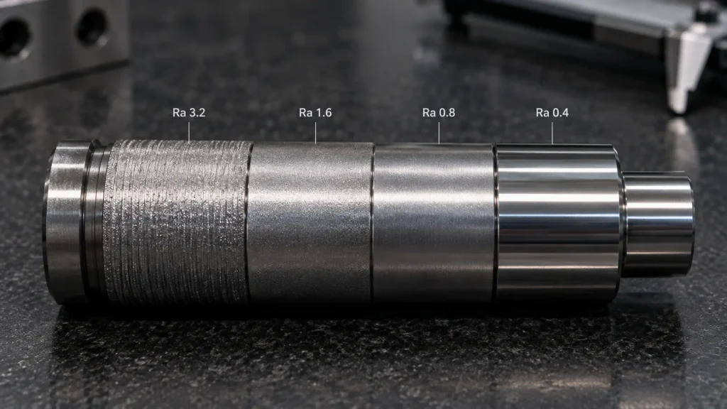
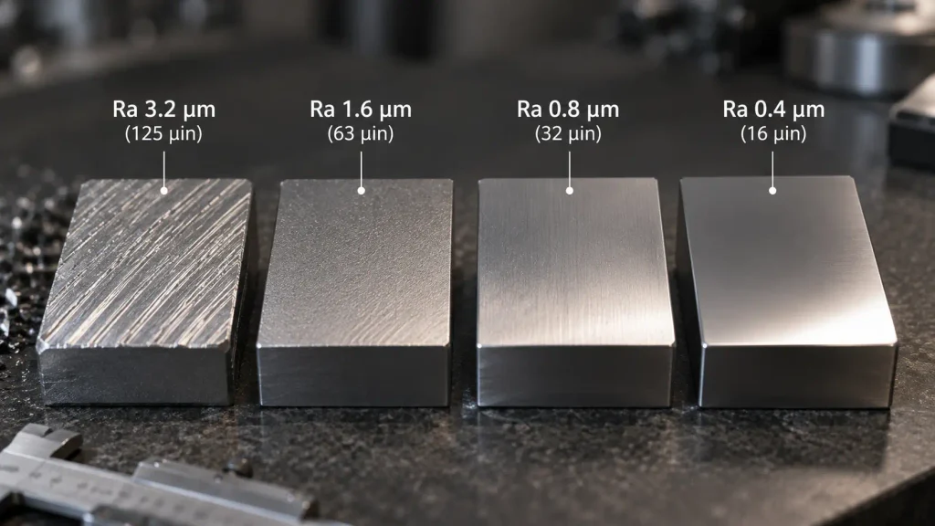
For common CNC-machined parts, 125 μin corresponds to Ra 3.2 μm, 63 μin to Ra 1.6 μm, and 32 μin to Ra 0.8 μm. These values are often more useful as process-planning references than as a simple ranking from “rough” to “good.” A lower Ra usually means a smoother average profile, but it can also mean additional finishing time, tighter process control, and more demanding inspection.
What Do Ra and Rz Actually Tell You?
Ra is the most widely used roughness parameter on machined drawings. It represents the arithmetic average of the profile deviations from the mean line over the evaluated length, which makes it useful for describing the overall roughness level of a surface with one number.
Rz describes the surface differently. It is a peak-to-valley height parameter and is more sensitive to larger local profile features than Ra. A surface may have a low average Ra while still containing a relatively deep groove, scratch, or pronounced peak. That difference matters when local defects affect sealing, sliding contact, fatigue initiation, or wear.
This is why Ra and Rz should not be treated as interchangeable specifications. Two surfaces can both measure Ra 0.8 μm but have different Rz values because their peak and valley structures are different. A turned surface with regular feed marks can have a different profile from a ground or milled surface even when the average Ra is similar.
For general machined faces, Ra often provides enough information. On critical surfaces, the designer may need to consider Rz, lay, waviness, or specific visual defects as well. Surface texture is more complex than a single average value.
Can Ra Be Converted Directly to Rz?
There is no universal Ra-to-Rz conversion factor. Approximate ratios are sometimes used during early manufacturing discussions, but they should not be used to accept a production part when the drawing specifies a particular parameter.
The relationship depends on how the surface is created. Milling produces toolpath and cutter marks, turning creates a feed-related profile, grinding produces an abrasive texture, and polishing removes material in a different way again. Tool wear, chatter, built-up edge, scratches, material tearing, and process instability can all change the peak-to-valley profile without producing the same proportional change in Ra.
If a drawing specifies Rz 6.3 μm, the surface should be measured and evaluated as Rz. A measured Ra value should not be multiplied by a general factor and treated as proof that the requirement has been met.
Approximate Ra-to-Rz relationships can still be useful when comparing process options or reviewing an early drawing, but they are planning tools rather than inspection criteria.
What Do 125, 63, 32, and 16 Surface Finishes Mean?
On inch-based engineering drawings, 125, 63, 32, and 16 normally refer to Ra measured in microinches.
| Surface Finish | Metric Ra | Typical Manufacturing Interpretation |
|---|---|---|
| 125 μin | 3.2 μm | General CNC-machined surface |
| 63 μin | 1.6 μm | Controlled finish machining |
| 32 μin | 0.8 μm | Fine machined functional surface |
| 16 μin | 0.4 μm | Precision finished surface |
A 125 finish is common for general machined faces where surface texture does not strongly control function. Housings, brackets, clearance faces, and many pocket surfaces can perform perfectly well at this level. A larger Ra number does not mean the part was machined poorly if the surface meets its functional requirement.
Moving toward 63 or 32 changes the manufacturing problem. Tool condition, feed, stepover, cutter geometry, vibration, and the finishing strategy become more important. A 32 finish may be produced directly by controlled turning or milling on suitable geometry, but the same Ra 0.8 μm requirement may be much harder to achieve on a flexible wall, deep pocket, or long internal bore.
At 16 μin, or Ra 0.4 μm, the process becomes more feature-dependent. Some turned diameters can reach this level directly, while other features are more reliably finished by grinding, honing, or another secondary process.
The practical difference between these values is therefore not simply how smooth the surface feels. It is how much manufacturing control is required to produce the finish consistently.
What Surface Roughness Can CNC Machining Achieve?
CNC milling and turning can produce a wide range of surface roughness. The actual result depends on the complete cutting system rather than the machine name alone.
| Process | Typical Practical Ra Range | Main Variables |
|---|---|---|
| Rough Milling | 3.2 to 12.5 μm | Feed, cutter geometry, rigidity |
| Finish Milling | 0.8 to 3.2 μm | Feed, stepover, tool condition, vibration |
| Rough Turning | 3.2 to 12.5 μm | Feed, insert geometry, material |
| Finish Turning | 0.4 to 3.2 μm | Feed, nose radius, speed, tool condition |
| Reaming / Fine Boring | 0.4 to 3.2 μm | Tool condition, allowance, alignment |
| Grinding | 0.1 to 1.6 μm | Wheel selection, dressing, feed |
| Honing | 0.05 to 0.4 μm | Abrasive, pressure, stroke |
| Lapping | 0.01 to 0.2 μm | Abrasive size, pressure, contact |
In milling, the programmed stepover and cutter geometry create a theoretical surface pattern, but the real finish is also affected by spindle runout, tool wear, material hardness, chip recutting, machine rigidity, and vibration. A large, well-supported face may reach Ra 0.8 μm with a stable finishing path, while the same program on a thin or flexible part can leave chatter or tool marks.
Turning is strongly influenced by feed per revolution and insert nose radius. A fine feed and suitable nose radius can produce a smooth profile, but built-up edge, poor chip control, long slender geometry, or worn tooling can quickly degrade the surface.
A CNC machining services supplier should therefore evaluate roughness together with material, feature geometry, dimensional tolerance, and inspection access. A Ra value alone is not enough to determine whether the finish is easy, difficult, or economically sensible.
Why the Same Ra Can Have Very Different Manufacturing Difficulty
Ra 0.8 μm on an exposed turned journal is not the same manufacturing requirement as Ra 0.8 μm at the bottom of a deep pocket.
The turned journal may be accessible with a rigid tool, short overhang, stable workholding, and a continuous finishing pass. The deep pocket may require a long tool extension, reduced cutter diameter, difficult chip evacuation, and lower rigidity. Both surfaces have the same specified Ra, but the second feature has much less process margin.
Internal features create similar problems. A long small-diameter bore may require fine boring, reaming, honing, or specialized tooling to obtain a consistent finish along its full length. A short external diameter with the same roughness requirement may be straightforward.
Part stiffness also matters. Thin walls and flexible features can move during the finishing pass, allowing vibration or deflection to leave surface marks even when the dimensional error appears small. Surface roughness can therefore become a stability problem rather than simply a cutting-parameter problem.
Inspection adds another constraint. A surface may be machinable to Ra 0.8 μm but difficult to verify if a profilometer stylus cannot reach the feature or cannot obtain the required traverse length. Deep grooves, narrow pockets, small bores, and interrupted surfaces should be reviewed for measurement access as well as machining capability.
This is why roughness should be reviewed by feature, not only by number.
Surface Roughness Does Not Replace Dimensional Tolerance or GD&T
A smoother surface is not automatically a more accurate surface.
Ra describes small-scale texture. It does not control the overall size, flatness, parallelism, cylindricity, runout, or position of the feature. A face can be polished to a very low Ra and still be out of flatness. A bore can have an excellent internal finish and still be outside its diameter tolerance.
A sealing face is a good example. The design may require Ra 0.8 μm to control local texture, but the face may also need a separate flatness requirement to prevent distortion across the sealing area. Improving Ra alone will not correct a warped or tapered surface.
The same principle applies to bearing journals. Surface roughness affects contact and lubrication, while diameter tolerance controls the fit and runout may control rotational behavior. These requirements solve different problems and should not be substituted for one another.
This distinction is important when drawings are reviewed for manufacturability. Tightening Ra is not a reliable way to compensate for an unclear dimensional or geometric requirement.
How Should Surface Roughness Be Selected for a Part?
Surface roughness should be selected from the function of the feature, not from the assumption that a smaller number is always better.
The following ranges can be useful as starting points during design review, but they are not universal acceptance criteria.
| Feature Type | Practical Starting Point | What Needs to Be Checked |
|---|---|---|
| General non-contact machined face | Ra 3.2 μm | Appearance, normal machining |
| General mating surface | Ra 1.6 to 3.2 μm | Contact, flatness, assembly |
| Bearing or sliding feature | Ra 0.4 to 1.6 μm | Lubrication, friction, wear |
| Sealing surface | Application-specific | Seal type, lay, scratches, flatness |
| Cosmetic surface before finishing | Process-specific | Blasting, anodizing, polishing, coating |
A non-contact housing face may gain nothing from Ra 0.4 μm. A bearing journal, sliding surface, or sealing feature may justify tighter roughness because the texture directly affects performance.
Mating faces should be evaluated together with geometric requirements. A surface that is extremely smooth but not flat may still produce poor contact. Bearing and sliding surfaces need consideration of lubrication and wear rather than simply the lowest Ra that can be machined.
Sealing surfaces deserve particular care because both the average roughness and the direction of the texture can matter. A low Ra value does not guarantee good sealing if a groove or scratch crosses the seal path.
The useful design rule is simple: specify the roughest surface that still satisfies the function.
How Does Surface Finish Affect Machining Cost?
Surface finish affects cost when the requirement changes the machining or inspection process.
A housing may contain twenty machined faces, but perhaps only one bearing bore and one sealing face require Ra 0.8 μm. If Ra 0.8 μm is applied globally, the remaining surfaces may also need dedicated finishing passes, slower cutting conditions, fresher tooling, and additional inspection even though the tighter finish provides no functional benefit.
A change from Ra 3.2 μm to Ra 1.6 μm may be handled within the normal CNC process on many features. Ra 0.8 μm can require smaller stepovers, reduced feeds, a dedicated finishing tool, improved vibration control, or another machining pass. At still lower values, grinding, honing, lapping, or polishing may become the more stable process.
The cost increase is therefore not tied to the Ra number itself. It comes from the extra process control required to produce and verify that number reliably.
For unusually low roughness requirements, ZH Precision can review the critical feature before production to determine whether the required finish is practical within the machining operation or whether a secondary finishing process provides better process stability.
How Do Surface Treatments Change the Meaning of a Roughness Requirement?
The surface produced by CNC machining may not be the surface that exists on the finished part.
Bead blasting changes the texture by creating a more uniform matte surface and reducing the visual directionality of machining marks. It does not simply lower Ra. Polishing removes surface peaks and machining marks, while anodizing grows an oxide layer on the aluminum substrate without removing significant scratches or chatter underneath.
Plating and coating processes add material to the surface. The final texture can depend on substrate preparation, coating thickness, deposition characteristics, and subsequent finishing.
A drawing that specifies Ra 0.8 μm on an anodized or plated feature should make clear whether that value applies to the machined substrate before finishing or to the final finished surface.
For parts that require both precision machining and surface finishing services, critical bearing seats, sealing faces, electrical contacts, threads, and close-tolerance fits may also require masking or selective finishing. The roughness requirement should be tied to the final functional surface, not just the machining stage.
How Should Surface Roughness Be Specified and Measured?
A useful roughness callout identifies the parameter, value, unit, and surface to which the requirement applies. A metric drawing may simply specify Ra 1.6 μm when no additional surface texture control is required.
Critical features may need more information. Lay direction can matter on sealing or sliding surfaces, and some applications may require an additional parameter such as Rz. The drawing should also avoid placing a tight requirement on a feature that cannot be inspected with the available measurement method.
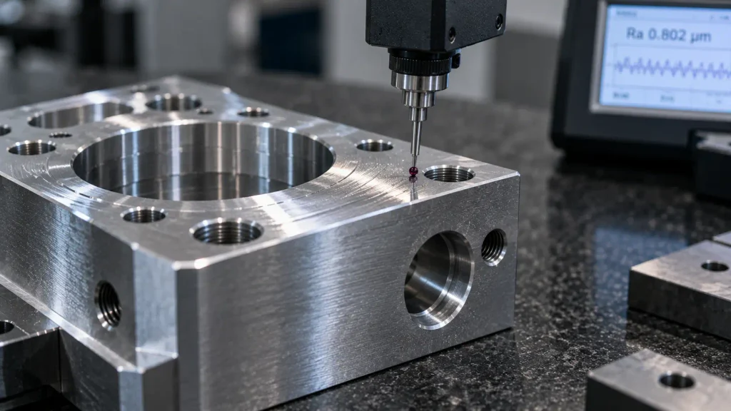
Surface roughness is commonly measured with a contact stylus profilometer. The stylus travels across the surface, records the profile variation, and calculates the specified roughness parameter. Optical methods are also used where the surface or geometry makes them appropriate.
Measurement direction should be considered when the surface has a strong lay. A stylus moving parallel to machining marks can produce a different result from one moving across them. The available evaluation length and probe access can also become limiting factors on small bores, narrow slots, deep pockets, or interrupted surfaces.
Current ISO surface texture specifications use the ISO 21920 series, while ASME B46.1 is widely used in U.S. engineering practice. Older drawings may still contain legacy N grades or references to earlier surface texture conventions, so the controlling drawing standard should be understood before inspection requirements are finalized.
Conclusion
A surface finish chart is useful for translating values such as 125, 63, 32, and 16 into Ra measurements, but the chart does not tell an engineer whether a particular roughness is necessary or how difficult it will be to manufacture.
Ra 3.2 μm is suitable for many general machined surfaces, while Ra 0.8 μm or lower may require tighter control of tooling, vibration, finishing strategy, and inspection. The same Ra value can also represent very different manufacturing difficulty depending on feature depth, rigidity, accessibility, and measurement conditions.
Ra and Rz describe different aspects of surface texture, and roughness should not be used as a substitute for dimensional tolerance, flatness, runout, or other geometric requirements. For most drawings, the better approach is to apply tighter surface requirements only where texture directly affects sealing, sliding, bearing contact, wear, appearance, or another functional condition.
FAQ
A 125 surface finish normally means 125 microinch Ra, which is approximately Ra 3.2 μm. It is commonly used for general CNC-machined surfaces where fine functional roughness is not required.
A 63 finish corresponds to approximately Ra 1.6 μm. It can often be produced by controlled finish milling or turning when the material, geometry, tooling, and machine conditions are suitable.
A 32 finish is approximately Ra 0.8 μm. It is commonly specified on selected functional features and normally requires greater control of tooling, feed, vibration, and finishing strategy than a general machined surface.
No. Ra and Rz describe different characteristics of the surface profile. Approximate ratios can be useful during preliminary process planning, but an Rz requirement should be measured and accepted as Rz.
Finish milling can commonly produce approximately Ra 0.8 to 3.2 μm on suitable features. The actual result depends on the material, cutter geometry, stepover, feed, tool condition, machine rigidity, vibration, feature geometry, and inspection requirements.




