

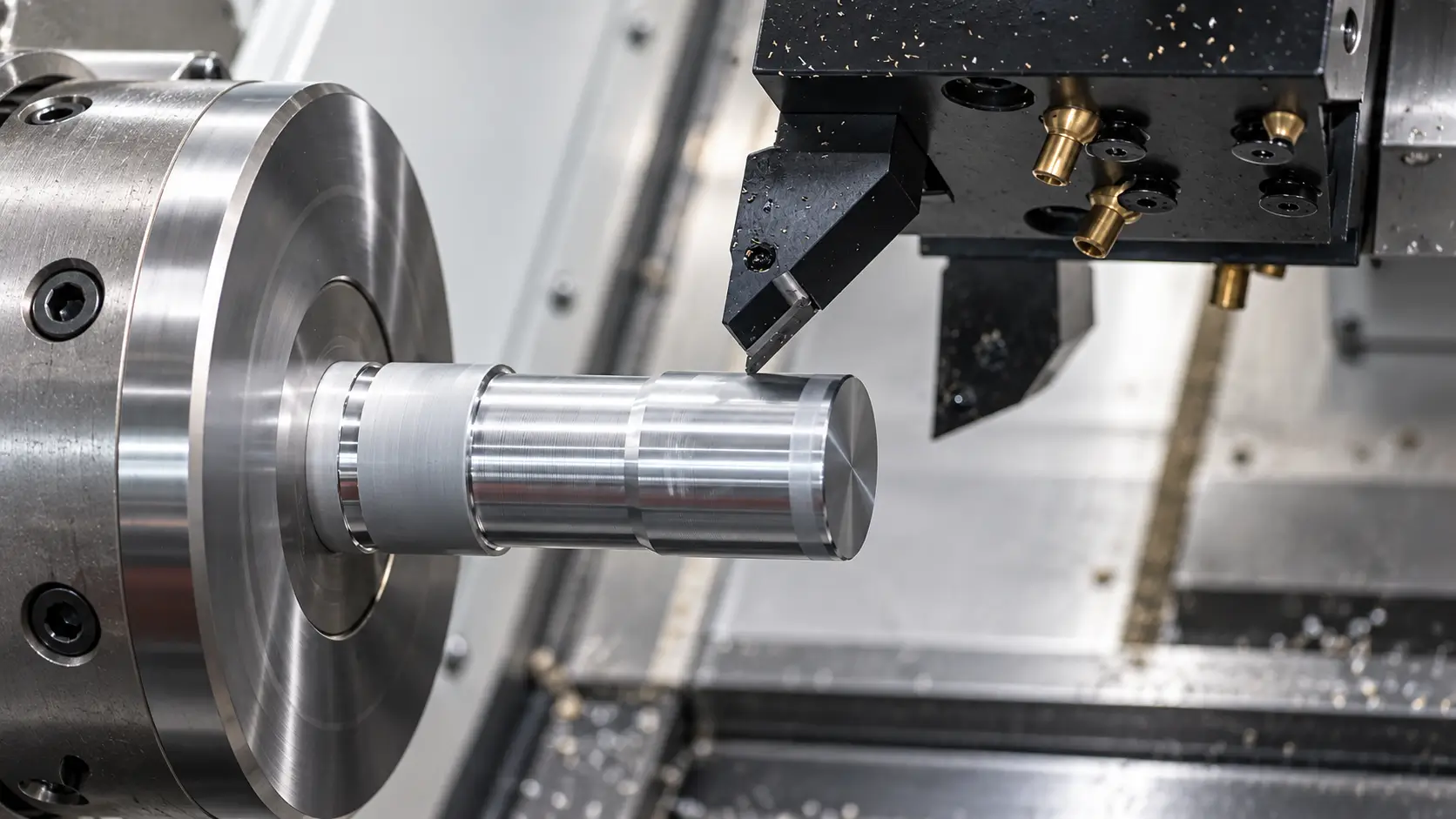
The important question is not simply whether a part looks round. CNC turning is most effective when important diameters, bores, shoulders, grooves, threads, and faces share a practical rotational axis. When those features can be machined from a stable setup, turning can produce several functional relationships without repeatedly repositioning the workpiece.
What Is CNC Turning?
In CNC turning, the workpiece is held in a chuck, collet, or other workholding system and rotated by the machine spindle. A cutting tool moves along a programmed path and removes material from the outside diameter, end face, or internal features until the required geometry is produced. This mechanical relationship between a rotating workpiece and controlled cutting tool defines the turning process.
Most conventional turning geometry is created through movements along the X and Z axes. Z movement follows the spindle axis and controls feature locations along the length of the part, while X movement changes the tool’s radial position and controls diameter. A stepped shaft, for example, can use these two movements to create several diameters, shoulders, grooves, chamfers, and end faces without changing the basic orientation of the workpiece.
This is why rotational geometry is more important than the overall shape of the finished component. A part may contain several different features and still be an excellent turning candidate if those features are referenced around the same centerline. Conversely, a component with one cylindrical bore but several large pockets and mounting faces may be much better suited to milling.
How Does CNC Turning Work?
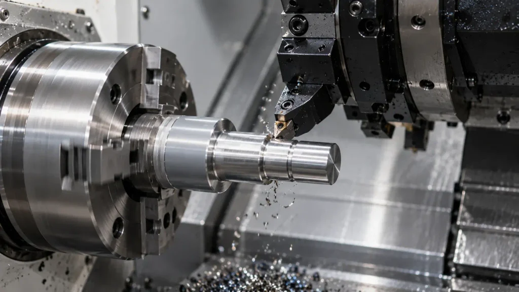
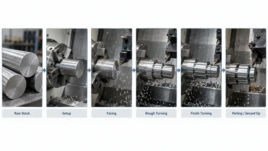
A CNC turning process usually begins with round bar, tube, a cut blank, forging, casting, or another suitable starting form. The workpiece is clamped and aligned with the spindle, while the CNC program defines tool positions, spindle speed, feeds, cutting depths, and the sequence in which features will be produced.
Machining commonly starts by facing the end of the stock to establish a controlled axial surface. Rough turning then removes most of the excess material from external diameters, leaving enough stock for finishing passes. Internal holes, bores, grooves, threads, chamfers, and other features are added as the part progresses through the machining sequence. Current process references describe turning in the same basic way, with a rotating workpiece and programmed tools producing external and internal rotational features.
The order of those operations affects more than cycle time. If a thin section is finished too early, later cutting forces may distort it. A deep bore may be better machined while the surrounding material still provides stiffness, while a critical diameter may need to be finished after most rough stock has already been removed and cutting stresses have been reduced.
Parts made from bar stock are often separated with a parting tool after the first side is completed. If the opposite end also requires machining, the component may be reversed and re-clamped for a second operation. That new setup introduces another locating condition, so features that must maintain close runout or axial relationships across both sides need to be considered during process planning rather than treated as independent dimensions.
What Is a CNC Turning Machine?
A CNC turning machine is a computer-controlled lathe that rotates the workpiece while positioning cutting tools relative to it. The machine normally includes a spindle, chuck or collet, turret, toolholders, and a CNC control system. Machine configuration determines how many features can be completed before the part must be transferred or re-clamped.
CNC Lathe vs CNC Turning Center
A basic CNC lathe is primarily designed for rotational machining using X and Z movement. It can efficiently perform external turning, facing, boring, grooving, threading, drilling, and parting operations when the required geometry remains accessible from the spindle axis.
A CNC turning center usually adds more capability around the same turning principle. Depending on the machine, this may include live tooling, C-axis spindle positioning, Y-axis movement, a secondary spindle, bar feeding, or automated part transfer. These functions allow more secondary features to be completed while the component remains inside the machine.
The distinction matters most when additional capability eliminates a meaningful setup. A simple shaft does not become a better part merely because it is machined on a more complex turning center. A connector containing turned threads, sealing diameters, wrench flats, and cross holes may benefit much more because several operations can potentially be consolidated.
Live Tooling and Secondary Operations
Live tooling allows selected turret tools to rotate independently while the spindle positions the workpiece. Combined with C-axis control, a turning center can perform operations such as radial drilling, tapping, slotting, and selected milling without moving the component to a separate milling machine.
Y-axis capability extends this further by allowing the tool to move away from the spindle centerline. Current turning-center configurations combine Y-axis, C-axis, live tooling, and in some cases a secondary spindle specifically to perform off-center milling, drilling, tapping, and back-side operations within the turning workflow.
These capabilities expand the range of parts that can be produced by turning, but they do not remove the underlying geometry constraint. A part dominated by large pockets, broad planar faces, and complex multi-directional surfaces may still be more efficiently produced on a milling center.
What Are the Main CNC Turning Operations?
CNC turning is not one cutting operation. Different tools and tool movements are used to create different functional features while the workpiece continues to rotate around the spindle axis.
| CNC Turning Operation | Main Purpose | Typical Features |
|---|---|---|
| Facing | Machines the end of the workpiece | End faces, axial reference surfaces |
| External Turning | Reduces or profiles the outside diameter | Shafts, steps, shoulders, tapers |
| Boring | Enlarges or finishes an existing internal hole | Precision bores, sleeves, bearing locations |
| Drilling | Produces an axial hole | Through holes, blind holes, starting holes |
| Reaming | Finishes a previously produced hole | Controlled hole size and surface condition |
| Grooving | Cuts a narrow recessed feature | O-ring grooves, retaining-ring grooves, reliefs |
| Threading | Produces internal or external threads | Fittings, shafts, connectors |
| Parting | Separates the part from stock | Bar-fed turned components |
| Live-Tool Machining | Produces secondary non-rotational features | Cross holes, flats, slots, tapped holes |
Turning, facing, grooving, parting, boring, drilling, and threading are established operations within the turning process.
The engineering issue is not simply whether a machine possesses each tool. Feature order, workholding stiffness, tool access, and the amount of material remaining around a feature determine whether those operations can be performed reliably. Two drawings containing the same operations can require very different machining strategies if one part is short and rigid while the other contains thin walls, deep internal features, or long unsupported sections.
What Parts Are Best Suited to CNC Turning?
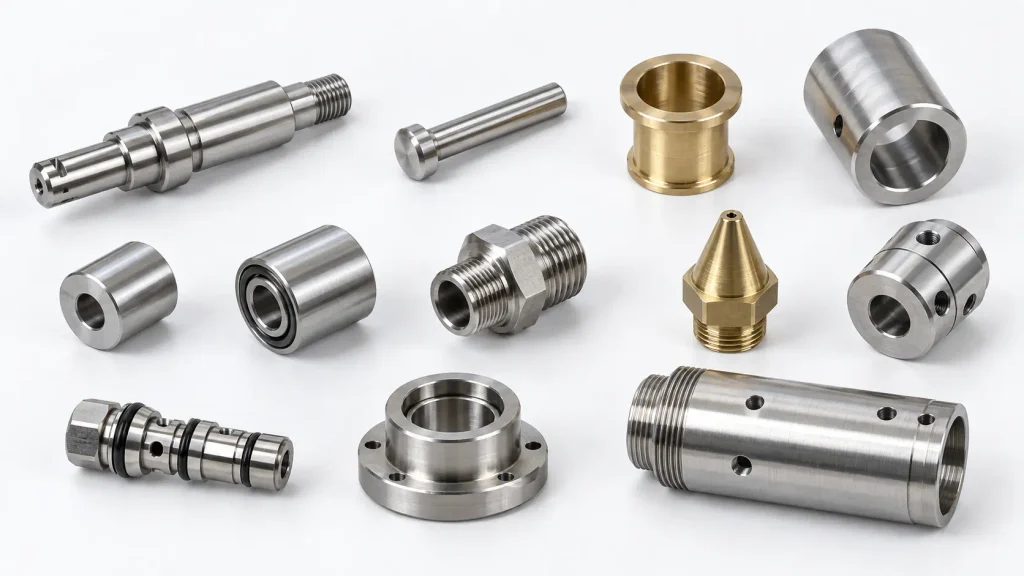
CNC turning is commonly used for shafts, pins, bushings, sleeves, spacers, rollers, fittings, nozzles, couplings, threaded connectors, valve components, bearing components, and cylindrical housings. These are common examples because much of their functional geometry is usually organized around a centerline.
The part name itself is not the deciding factor. Consider a shaft containing two bearing diameters, a shoulder, an external thread, a retaining-ring groove, and an axial bore. Although these features perform different functions, they can all be related to the same spindle axis, allowing the turning process to establish several of them without changing the basic workpiece orientation.
A component becomes less naturally suited to turning as more critical geometry moves away from that axis. Large pockets, broad mounting surfaces, irregular contours, and holes requiring access from several directions increasingly favor milling. A turned connector with two wrench flats may still suit a live-tool turning center, while a rectangular housing containing one precision bore is usually better treated as a milling component.
This axis-based view is more useful than the common rule that “round parts are turned.” A component can appear cylindrical yet still require extensive milling, while a more complicated-looking component may remain a strong turning candidate if most important features share the same rotational reference.
What Materials Can Be CNC Turned?
Aluminum, stainless steel, carbon and alloy steels, titanium, brass, copper, and many engineering plastics can all be CNC turned. The process principle remains the same, but cutting behavior changes substantially between materials.
Aluminum generally allows efficient material removal and good chip control when the correct tools are used. Stainless steel can create higher cutting loads and work-hardening concerns, while titanium places greater emphasis on heat management and tool wear. Brass is usually highly machinable, whereas copper behavior varies more strongly by grade and can create challenges with burrs, chip formation, and surface condition.
Engineering plastics introduce a different set of problems. Lower stiffness, thermal expansion, and sensitivity to clamping pressure mean that a dimension can change because of cutting heat or workholding even when tool positioning is correct. Material selection should be evaluated together with geometry and tolerance rather than assuming that every machinable material behaves similarly.
These differences are why CNC machining materials influence not only the raw-material cost, but also tool selection, machining time, chip control, dimensional stability, and achievable surface condition.
CNC Turning vs CNC Milling
The fundamental difference between CNC turning and CNC milling is where the primary rotation occurs. In turning, the workpiece rotates while the tool moves relative to it. In milling, the cutting tool rotates while the workpiece is normally secured in a fixture.
That mechanical difference determines which geometry each process handles efficiently. Diameters, bores, shoulders, grooves, tapers, and threads arranged around a centerline naturally favor turning. Pockets, broad planar surfaces, slots, irregular contours, and features approached from several directions generally favor milling.
The distinction between CNC milling and CNC turning becomes most useful when it is based on feature orientation rather than the outside silhouette of the part. Components that contain meaningful amounts of both geometry types may be produced through separate operations or on a turn-mill machine that combines them within one manufacturing route.
When Does CNC Turning Become Difficult?
Long and slender parts become harder to turn as unsupported length increases relative to diameter. Cutting forces can push the workpiece away from the tool, causing taper, vibration, or inconsistent diameter along the shaft. Tailstock support, steady rests, lower cutting loads, and a revised roughing sequence can improve stability. The practical limit is not simply whether the part fits within the machine’s maximum turning length, but whether it remains rigid enough while material is being removed.
Deep internal bores create the same stiffness problem on the tool side. A boring bar must extend far enough into the component to reach the internal surface, and greater overhang makes the tool more susceptible to deflection and vibration. A small-diameter deep bore may be substantially more difficult than a shallow bore carrying the same nominal tolerance because available tool diameter and rigidity are much more restricted.
Thin rings and sleeves are particularly sensitive to workholding. Excessive chuck pressure can compress a thin cylindrical wall while it is being machined, allowing the diameter to measure correctly in the clamped condition but change after the jaws release. Soft jaws, greater contact area, controlled cutting loads, temporary supporting material, or a different operation sequence may be needed to keep the finished geometry stable.
Multiple chucking operations create a different source of variation. Removing, reversing, and re-clamping a component establishes a new locating condition, which matters when features machined on opposite sides must maintain runout, coaxial, or axial relationships. Second-operation turning is routine, but the manufacturing plan should identify which functional relationships cross that setup boundary.
How Should Engineers Design Parts for CNC Turning?
A turned-part drawing should distinguish between dimensions that define function and dimensions that only define nominal shape. A bearing seat, seal diameter, locating bore, or thread may need controlled dimensions, while a clearance diameter or non-functional surface may not require the same tolerance. Applying equally tight requirements to every turned feature adds machining and inspection effort without necessarily improving the assembly.
Feature relationships can be more important than individual dimensions. Two diameters may each meet their size tolerances while still creating an assembly problem if excessive runout exists between them. A bore and outside diameter may likewise need to share a controlled axis even when both nominal sizes are relatively easy to machine.
Internal geometry should account for tool access and rigidity. A deep small-diameter bore restricts boring-bar size, while an unnecessarily deep thread increases tool engagement without adding useful thread strength once the required functional engagement has been reached. Grooves close to thin walls can also reduce local stiffness and make later finishing operations more difficult.
The second side of a turned component deserves equal attention. When critical features must be machined after the part is reversed, the drawing should make the intended datum relationship clear enough for the machining and inspection strategy to preserve it. Runout, axial location, bore alignment, and mating interfaces are easier to control when their functional relationship is understood before the setup is planned.
For drawings that combine critical diameters, deep bores, threads, runout requirements, or secondary milled features, ZH Precision’s custom CNC turning services can include a manufacturability review before production to evaluate setup, workholding, tooling, and inspection requirements.
Conclusion
CNC turning is a computer-controlled machining process in which the workpiece rotates while cutting tools create external and internal geometry. It is especially effective for parts containing diameters, bores, shoulders, grooves, tapers, threads, and faces that share a practical rotational axis.
The value of the process comes from more than producing round shapes. When related features can remain referenced to the same spindle axis, turning can reduce unnecessary repositioning and maintain important dimensional relationships through a relatively direct manufacturing route. Modern turning centers extend that capability with live tooling, additional axes, secondary spindles, and automated part transfer.
For process selection, the most useful question is not simply whether a component looks cylindrical. It is whether its important features can be reached, supported, and machined efficiently around a stable rotational reference.
FAQ
CNC turning is a subtractive machining process in which a workpiece rotates while computer-controlled cutting tools remove material. It is primarily used to produce cylindrical and rotational features such as diameters, bores, grooves, shoulders, tapers, and threads.
A CNC turning machine is a computer-controlled lathe that rotates the workpiece and automatically positions cutting tools. Basic machines primarily perform turning operations, while more advanced configurations may also include live tooling, additional axes, bar feeding, and secondary spindles.
A CNC turning center is generally a more capable form of CNC lathe that can combine conventional turning with additional machining functions. Depending on the machine, these may include C-axis positioning, Y-axis movement, live-tool drilling or milling, and back-side machining with a secondary spindle.
CNC turning is used for parts whose main functional features are arranged around a rotational axis. Common examples include shafts, bushings, pins, sleeves, rollers, fittings, connectors, valve components, and threaded parts.
Common CNC turning operations include facing, external turning, boring, drilling, reaming, grooving, threading, and parting. Turning centers equipped with live tooling can also perform selected drilling, tapping, slotting, and milling operations.
CNC turning rotates the workpiece while cutting tools move relative to it, making the process suitable for rotational geometry. CNC milling rotates the cutting tool while the workpiece is normally held stationary, which is better suited to pockets, flat surfaces, slots, irregular contours, and multi-directional features.
Yes. Turning centers equipped with live tooling, C-axis positioning, and additional axes can produce features such as cross holes, flats, slots, and off-center holes. If non-rotational geometry dominates the component, milling or a combined turn-mill process may be more appropriate.
Common materials include aluminum, stainless steel, carbon and alloy steel, titanium, brass, copper, and engineering plastics. Each material requires an appropriate combination of tooling, cutting parameters, workholding, and process control because heat generation, chip behavior, stiffness, and tool wear differ.




