

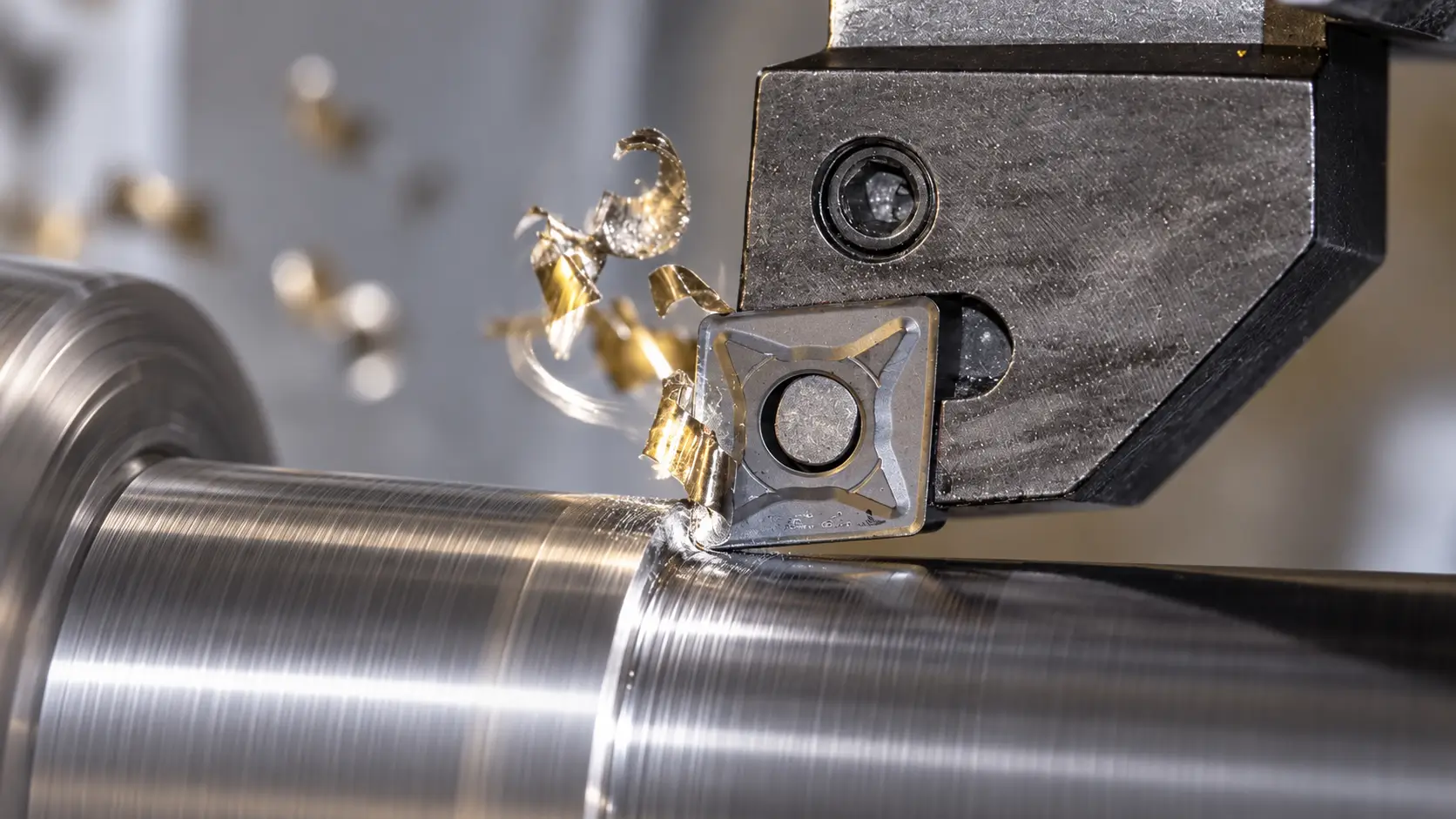
Tool wear is therefore more than a question of how long an insert or end mill lasts. The location and shape of the wear can reveal what is happening at the cutting edge, while changes in the machined part show when that wear has become significant to the process. Understanding both sides makes it easier to distinguish normal wear from a machining condition that needs correction.
What Is Tool Wear in Machining?
Tool wear is the gradual loss, deformation, or deterioration of material at a cutting edge during machining. It develops because the tool is exposed to repeated mechanical contact, high localized pressure, friction, heat, and interaction with the workpiece and flowing chip.
Some degree of wear is normal. A cutting edge does not remain geometrically identical throughout its service life. The practical question is whether the wear develops predictably and whether the tool can continue producing parts within the required dimensional and surface requirements.
Progressive wear should also be distinguished from sudden edge damage. A tool can have a measurable flank wear land and still cut consistently, while another tool may chip unexpectedly and cause an immediate change in part dimensions. Catastrophic fracture is different again. These conditions may all appear on a worn tool, but they do not necessarily have the same cause or require the same response.
How to Recognize the Main Tool Wear Patterns
Different regions of the cutting edge experience different contact conditions. For that reason, the position of the wear is often as useful as its severity.
| Wear pattern | Typical location | What it can indicate |
| Flank wear | Clearance face behind the cutting edge | Progressive rubbing, abrasion, or normal tool deterioration |
| Crater wear | Rake face beneath chip flow | High temperature and strong chip-tool interaction |
| Notch wear | Near the depth-of-cut line | Localized loading, work-hardened surface, scale, or material variation |
| Edge chipping | Along the cutting edge | Mechanical instability, impact, overload, or interrupted cutting |
Flank Wear
Flank wear develops on the clearance face that passes close to the newly machined surface. As the wear land grows, contact between the tool and workpiece increases and the effective condition of the cutting edge changes.
A moderate and relatively uniform flank wear pattern can be part of normal tool life. It becomes more important when it begins to alter the finished dimension, increase cutting force, or deteriorate surface quality.
For this reason, flank wear is particularly relevant in finishing operations. The tool may still appear capable of cutting, but its condition may no longer be stable enough for a close-tolerance feature.
Crater Wear
Crater wear forms on the rake face where the chip moves across the tool. That location places it under high pressure and, depending on the material and cutting conditions, very high temperature.
Its mechanism is therefore different from simple rubbing against the machined surface. Thermal and chemical interaction between the workpiece material, chip, coating, and tool substrate can become important.
A growing crater can weaken the cutting edge by reducing the amount of material supporting it. If the crater progresses far enough toward the edge, the risk of chipping or sudden failure can increase even when flank wear is not excessive.
Notch Wear and Edge Chipping
Notch wear is concentrated near the depth-of-cut line rather than distributed evenly along the cutting edge. It can be associated with work-hardened surfaces, scale, abrasive material, or repeated loading at the same contact boundary.
Edge chipping is less progressive. Small sections of the cutting edge break away, which can produce a sudden change in cutting behavior. Interrupted cuts, poor rigidity, excessive mechanical loading, unstable inserts, or unsuitable tool geometry can all contribute.
This distinction matters when diagnosing a machining problem. A slowly developing wear land and a newly chipped cutting edge may produce similar defects on the part, but the process corrections are unlikely to be the same.
Why Cutting Tools Wear During Machining
Cutting speed, feed, depth of cut, coolant, tool coating, and workpiece material all affect tool life, but they are not wear mechanisms by themselves. Their importance comes from how they change temperature, pressure, sliding contact, chip formation, and mechanical loading at the cutting edge.
Abrasive wear occurs when hard constituents in the workpiece or chip mechanically remove tool material. Hard particles, carbides, scale, or abrasive inclusions can accelerate this process. In these conditions, simply improving coolant flow may reduce heat but will not remove the underlying abrasive contact.
Adhesive wear develops when material repeatedly bonds and separates at the tool-workpiece or tool-chip interface. Small amounts of tool material may be pulled away during this process. Built-up material on the edge can also form and break away, sometimes taking part of the cutting edge with it.
At higher cutting temperatures, diffusion and chemical interaction can become more influential for certain combinations of tool and workpiece materials. This is one reason increasing cutting speed can shorten tool life even when the cut remains mechanically stable. The higher temperature changes what is happening at the interface.
Mechanical and thermal cycling can create another problem. Milling, interrupted turning, variable engagement, or unstable cutting conditions repeatedly load and unload the edge. Instead of producing smooth progressive wear, the process may encourage thermal cracking or chipping.
This is why a visible wear pattern should not be treated as an isolated defect. It is evidence of the cutting conditions that produced it.
When Tool Wear Starts to Affect the Part
The end of useful tool life does not necessarily occur when the tool can no longer remove material. In many CNC operations, the tool becomes unsuitable earlier because the part is no longer being produced consistently.
Dimensional drift is one of the most important examples. As the edge changes, effective tool geometry, cutting force, and deflection can also change. A turned diameter may begin to move gradually in one direction even though the program and toolpath remain unchanged. In milling, similar effects can appear in wall position, bore size, slot width, or feature geometry.
Surface condition can change at the same time. Increased rubbing, built-up material, edge deterioration, or chipping may leave a rougher or less consistent surface. Burr formation can also increase as the edge loses sharpness.
This relationship is especially important in CNC precision machining, where process stability matters as much as the nominal machine position. A tool can still be cutting while no longer providing the variation control needed for a critical dimension.
Tool wear, however, should not become the automatic explanation for every dimensional problem. Workholding movement, thermal growth, material stress, spindle runout, tool deflection, and measurement variation can produce similar symptoms. A stronger indication of wear-related drift is a repeatable dimensional trend that develops with tool usage and changes after a controlled tool replacement or offset correction.
That distinction matters because compensating for the wrong cause can hide a process problem instead of correcting it.
What the Wear Pattern Can Tell You About the Process
A useful diagnosis starts by separating gradual change from sudden change.
If dimensions move progressively over a series of parts while the fixture, machine temperature, and measurement method remain stable, normal tool deterioration becomes a reasonable place to investigate. If a new tool or insert restores the dimensional trend, that evidence becomes stronger.
A sudden dimensional step is different. If the first twenty parts remain stable and the next part changes abruptly, progressive flank wear alone is less convincing. Edge chipping, insert movement, fixture movement, contamination at a locating surface, or another discrete event may deserve attention first.
Surface finish can provide another clue. A gradual increase in roughness together with a consistent dimensional trend can point toward progressive edge deterioration. A sudden scratch, torn surface, or isolated finish defect may indicate chip recutting or local edge damage instead.
The location of the wear can then narrow the investigation. Uniform flank wear may lead to a review of cutting time, material abrasiveness, speed, and tool grade. Heavy crater wear moves the focus toward temperature and chip-tool interaction. Localized notch wear suggests looking more closely at the depth-of-cut line, surface condition, work hardening, or repeated localized loading.
This is more useful than treating every worn tool in the same way. The appearance of the edge is part of the process evidence.
How to Slow Tool Wear Without Creating Another Machining Problem
Extending tool life is useful only when the adjustment still produces an acceptable part. A parameter change that reduces visible wear but creates chatter, poor chip control, long cycle time, or dimensional instability has not improved the overall process.
Cutting speed is a common example. Reducing speed can reduce temperature and extend tool life in many operations, but the lowest possible speed is not automatically the best condition. The tool still needs to cut efficiently, form manageable chips, and maintain a stable surface.
Feed and engagement also need to be considered together. An excessively light cut can increase rubbing instead of producing an efficient chip, while excessive engagement can raise cutting force and edge temperature. The correct range depends on tool geometry, workpiece material, rigidity, and the type of operation.
Tool material and coating should match the dominant wear mechanism. A coating that performs well in one material or temperature range may not provide the same benefit in another. Changing coating without understanding whether the problem is abrasion, temperature, adhesion, or edge instability can produce little improvement.
Coolant has a similar limitation. Adequate coolant can help control temperature, reduce friction, and remove chips, but it cannot compensate for poor workholding or an unstable tool assembly. If the primary cause is vibration or excessive tool overhang, increasing coolant flow does not address the underlying problem.
Rigidity therefore remains important. Shorter tool projection, stable holders, secure inserts, appropriate workholding, and controlled cutting engagement can reduce vibration and impact loading. This is particularly important when chipping is occurring rather than uniform wear.
The objective is not simply to make the tool last longer. It is to make the wear rate predictable enough that part quality remains controlled.
When Should a Cutting Tool Be Replaced?
There is no single wear value or cutting time that defines the correct replacement point for every operation.
A roughing tool may remain useful with wear that would already be unacceptable on a finishing tool. A feature with a broad dimensional tolerance may also tolerate more tool deterioration than a bore, locating diameter, or sealing surface with a close requirement.
For one-off or prototype work, inspection can sometimes guide the decision directly. If the feature remains within specification and the edge condition is stable, the tool may continue cutting.
Repeat production benefits from a different approach. Once a consistent relationship has been established between tool usage, wear, dimensional drift, and surface condition, a planned replacement point can prevent the process from reaching an unstable stage.
This is often more valuable than extracting the maximum possible life from every cutting edge. A tool that lasts five more parts but creates unpredictable inspection failures may cost more than replacing it earlier.
For close-tolerance production, the useful end of tool life is therefore often defined by process capability, not by physical tool failure.
Process Control for Repeat CNC Production
In repeat CNC production, tool wear should be managed as a process variable rather than discovered after a part fails inspection. Stable production requires defined cutting conditions, appropriate tool-change intervals, and inspection of critical features so dimensional trends can be identified before they exceed tolerance.
ZH Precision supports custom CNC machining with process planning, in-process inspection, CMM verification, and controlled tool replacement based on part and tolerance requirements. This helps maintain more consistent results across low-volume and repeat production runs.
Conclusion
Tool wear is unavoidable, but unstable tool wear is not. Flank wear, crater wear, notch wear, and edge chipping develop under different contact and loading conditions, so they should not be treated as interchangeable symptoms.
The most useful way to evaluate a worn tool is to connect three pieces of evidence: the wear pattern on the cutting edge, the cutting conditions that produced it, and the trend visible in the finished parts. That relationship makes it easier to decide whether the process needs a parameter change, a different tool condition, or investigation somewhere else entirely.




